
Previous Story
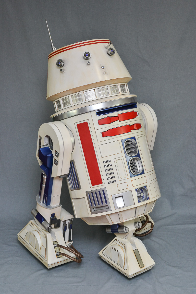
3D Printed R5-D4 Dome
 Who can forget the depressed, sickly looking R5 unit on the Jawa Sandcrawler. This poor little droid looks like it’s had more than its share of bad luck. As R5-D4 is “adopted” by the Lars family on Tatooine, it happily warbles to itself has it rolls towards Luke. Just when it thinks it’s luck is about to change…dun dun dun…bad motivator 🙁 R5 is carried back into the Sandcrawler.
For those of you that are thinking about constructing an R5-D4 astromech, or if you are looking for an easy way to convert your R2 unit into R5, consider checking Mr. Baddeley’s R5 dome available on thingiverse.com. If you are printing on a smaller bed, Mr. Baddeley has a revised set of files that will fit on a smaller bed.
Printing
Head over to Thingiverse, and grab all of the files. If you’d like to thank Mr. Baddeley for his hard work, consider becoming a supporter on his Patreon site.
I used a Creality CR-10S to print the dome pieces. I used PLA+ filament in white, at a layer height of .20mm. I used just over 2 spools of filament. For the smaller, more detailed pieces, such as the eyes, buttons, and rods, I printed at a .12mm layer height. Why the difference in layer heights for these pieces? I know for a fact that I will need to sand and fill the dome. I chose a .20mm layer height as a nice balance between speed and quality. For the smaller items that are more difficult to sand, I will use a smaller layer height to capture more of the detail.
Assembly
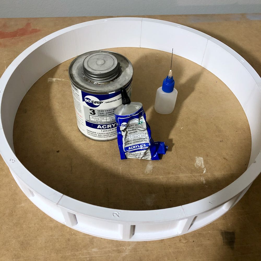
I decided to build from the bottom up. All of the pieces are numbered, and should be assembled in numerical order. As you can see here, the dome ring is numbered 1-7.
For the initial bond, I used a syrupy adhesive that is excellent for use on PLA. SCIGrip #16 was placed on the connection points. This adhesive has a 5 minute working time. To really fuse the pieces together, I used a needle applicator to get between the joints, and applied SCIGrip #3. This has a much shorter working time of 1 minute. I used this to fuse my R2 body skins to the ribs, it is VERY strong. After 2 years of lugging R2 around in the car, going to various events, being touched, it is still holding up strong. I am a believer in this stuff.
Next, I assembled the ring that sits on top of the dome ring. These pieces are also numbered. I used SCIGrip #16 for the initial bond, and then when the entire piece was assembled, I drizzled SCIGrip #3 on the joints. SCIGrip will melt the PLA, try to avoid spilling it onto visible areas.
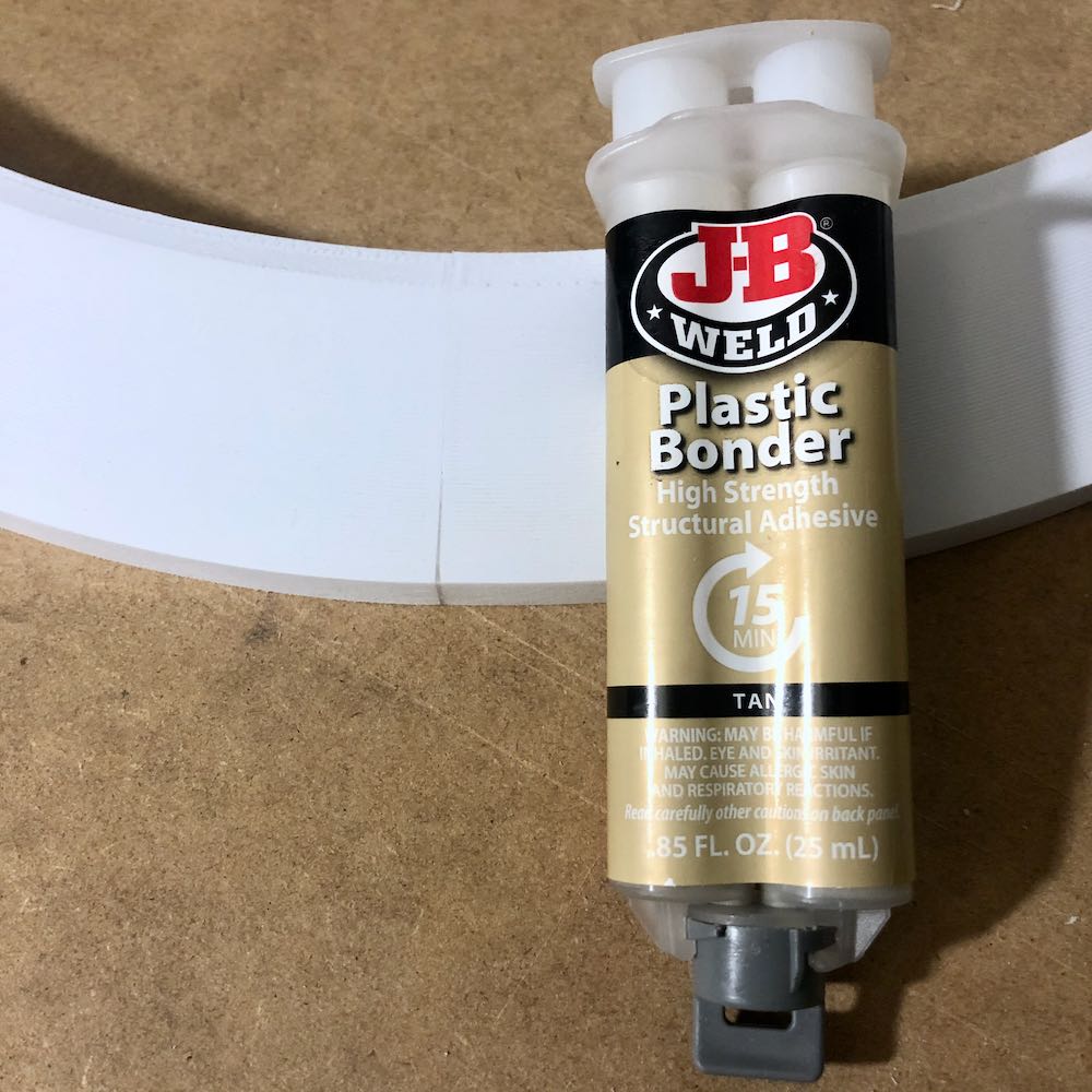
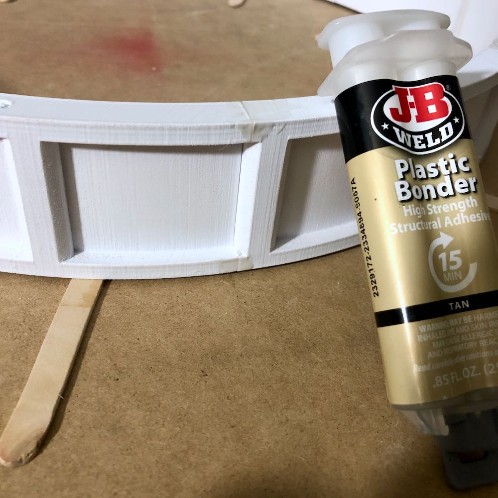
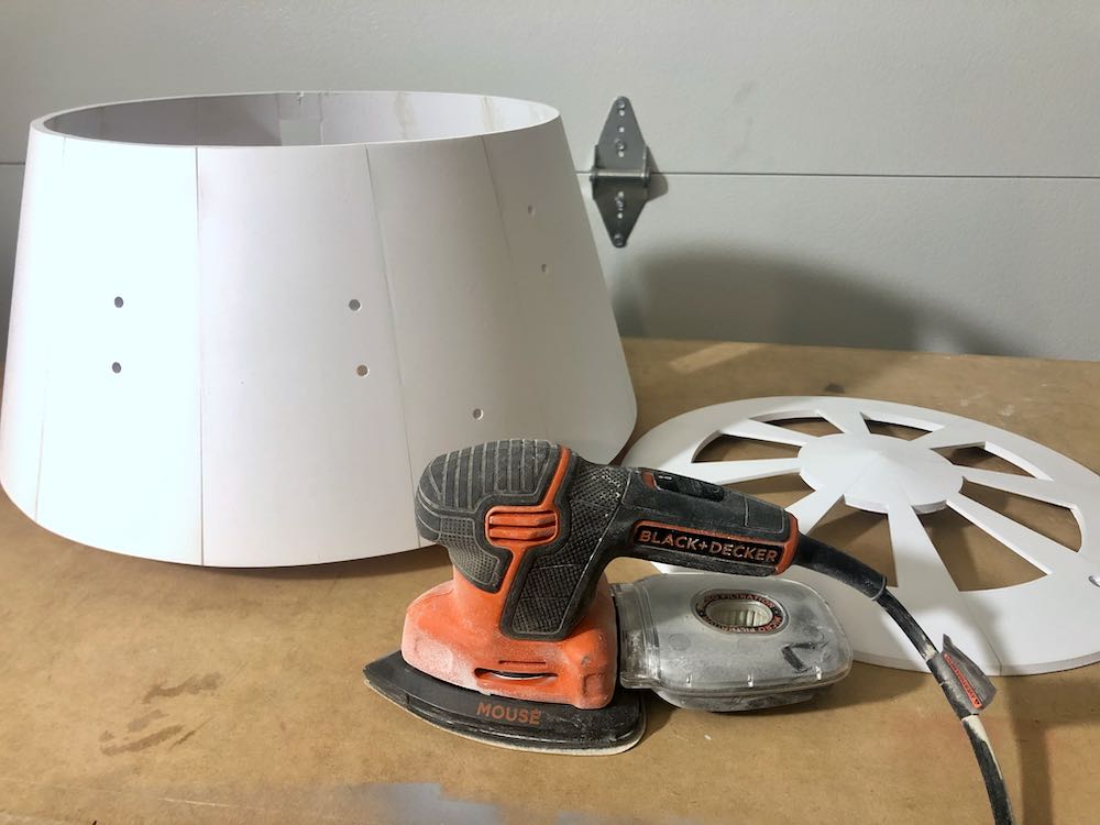
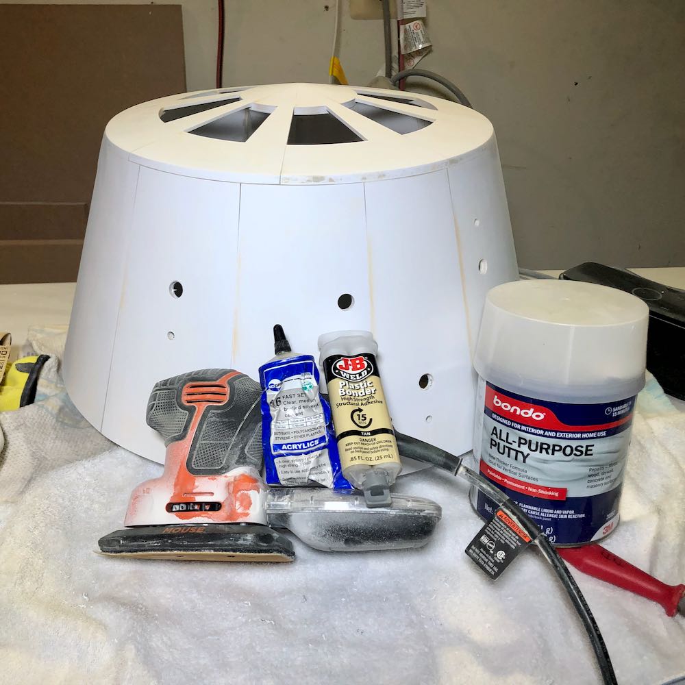
I want these bonds to be as secure as possible. It is heartbreaking when you finish painting your product and you see a crack staring at you because of a weak joint. I did have a few gaps that required filling. If this was a gap in the middle of the plastic, I would use wood filler putty or Bondo. Because this is a joint, I chose to go with plastic bonder epoxy. I filled in all the visible gaps to reinforce the joints. Epoxy is can be difficult to sand, so try to remove the excess before it cures. In the image below, you can see epoxy filled in the joint. After the rings were assembled, the ridges were knocked down with 120 grit sandpaper. I used a mouse sander.
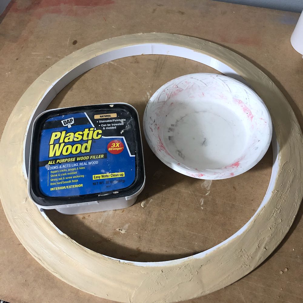
When finishing 3D prints, I fight on 2 fronts. I sand the lines down with 120 grit, and then apply wood filler putty. I add a dash of water to give the putty a toothpaste-like consistency. It is then brushed on with a chip brush. After leaving it overnight, I use a mouse sander with 220 grit to remove the putty. I like to think of this as meeting in the middle. 120 grit takes the ridges down, the filler putty fills in any remaining ridges. The mouse sander definitely saves time.
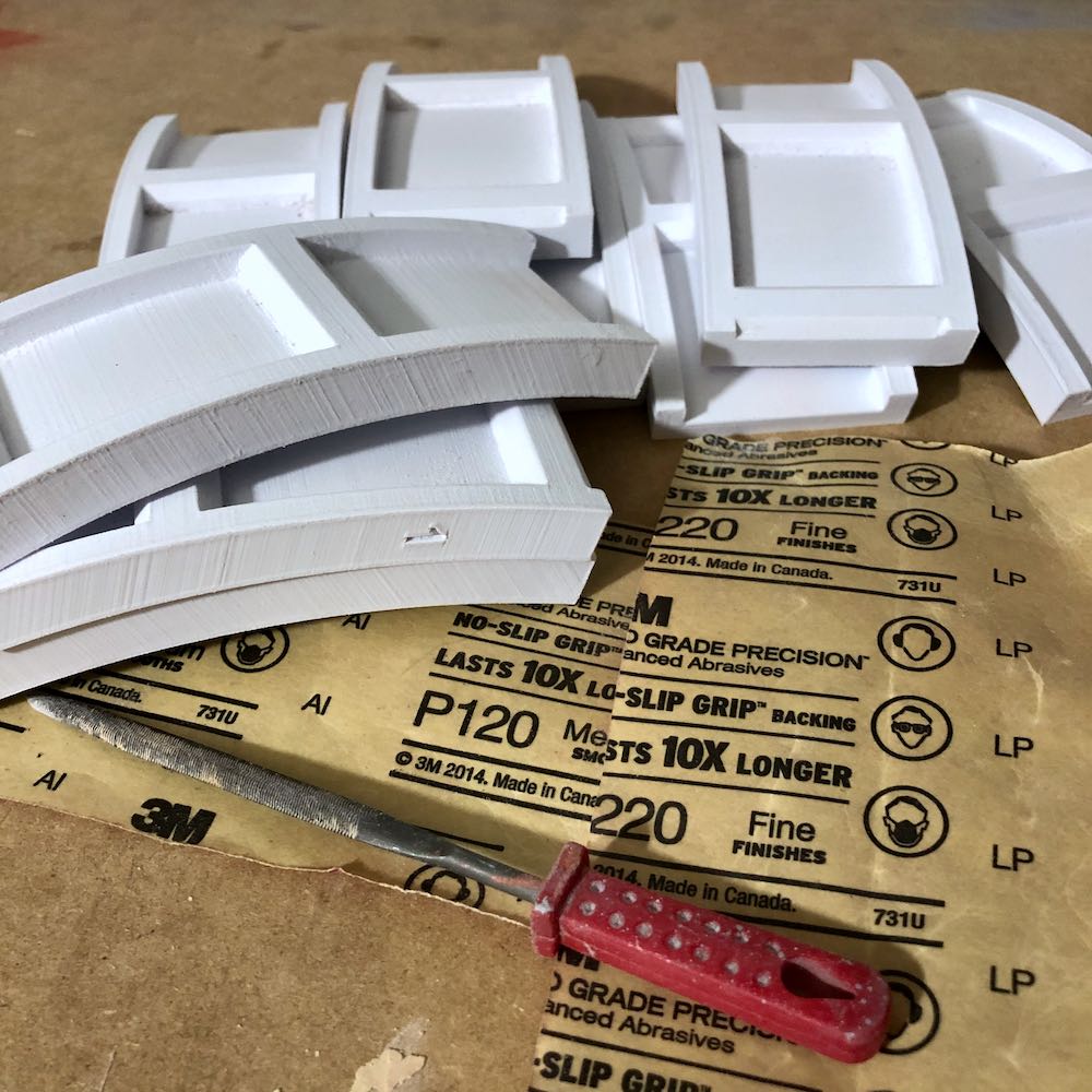
Moving my way up, I began working on the “ladder” ring. Because this ring has some hard-to-reach areas, I chose to begin sanding prior to assembly. I used a small file, along with 120 & 220 grit sandpaper. The “window” areas of the ladder will be covered, so they do not need to be filled with putty.
Once the ladder pieces were sanded, they were assembled in numerical order. SCIGrip #16 was used for the initial bond, followed by SCIGrip #3 with the needle applicator.
You guessed it, plastic bonder epoxy was used to fill any visible gaps between the joints.
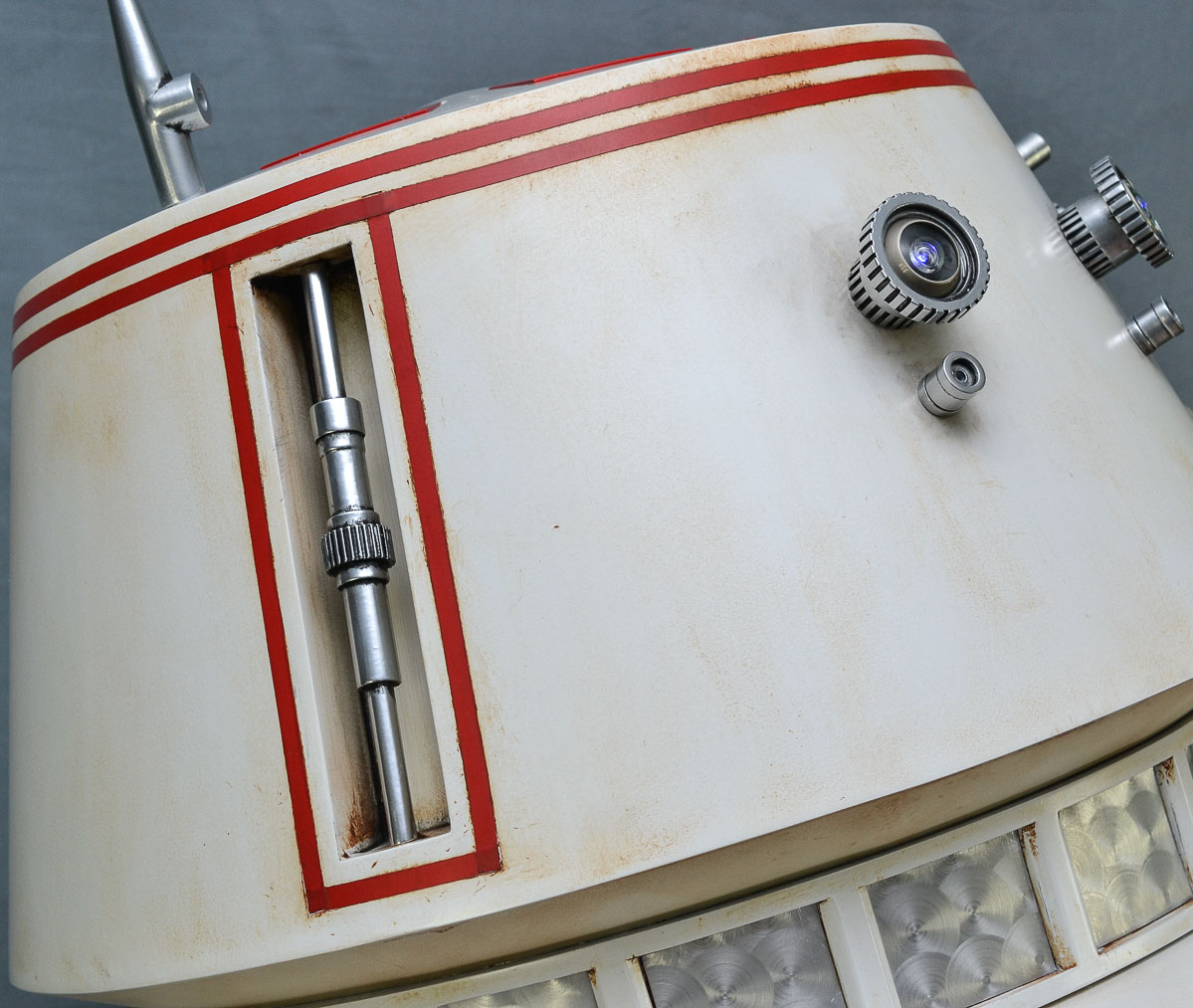
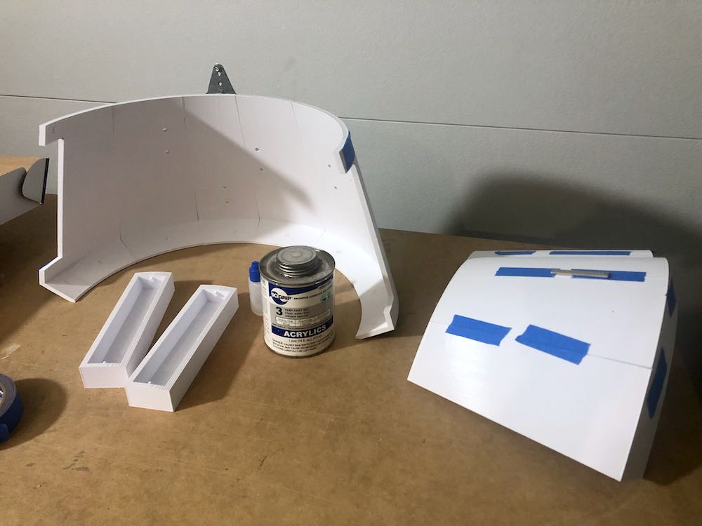
The main dome was assembled in 3 different sub-sections, with the rod boxes dividing the sections. I assembled the “face” first in numerical order, and then the right-rear and left-rear dome sections. After those 3 were assembled, I attached the smaller pieces that allow for the rod boxes. I did not install the rod boxes just yet. Once the smaller pieces were in place, I connected the 3 sub-sections. SCIGrip #16 and #3 were used. Magnets and tape were used to hold the pieces in place.
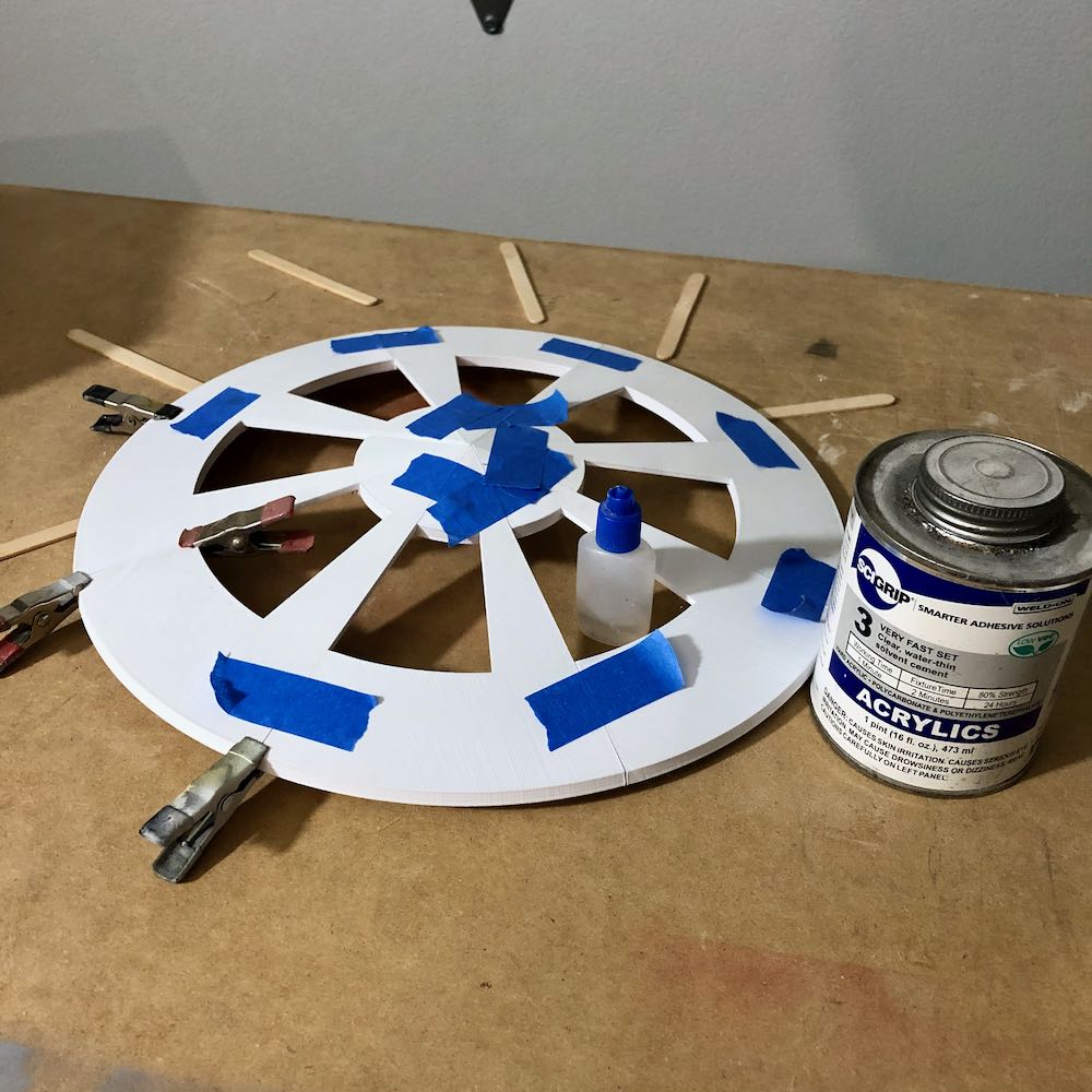
Whew, made it to the top. No surprises here. The top dome pieces were sanded with 120 grit and then glued together with SCIGrip #16 and #3.
Epoxy to the rescue for gap filling between the joints.
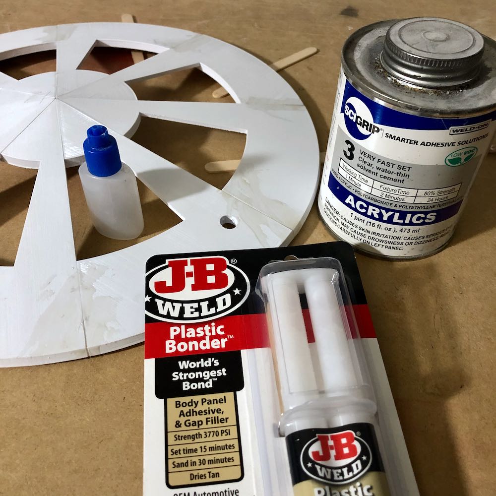
The assembled pieces were sanded with 120 grit sandpaper via mouse sander. This helped take down 3d print ridges, and also remove excess epoxy.
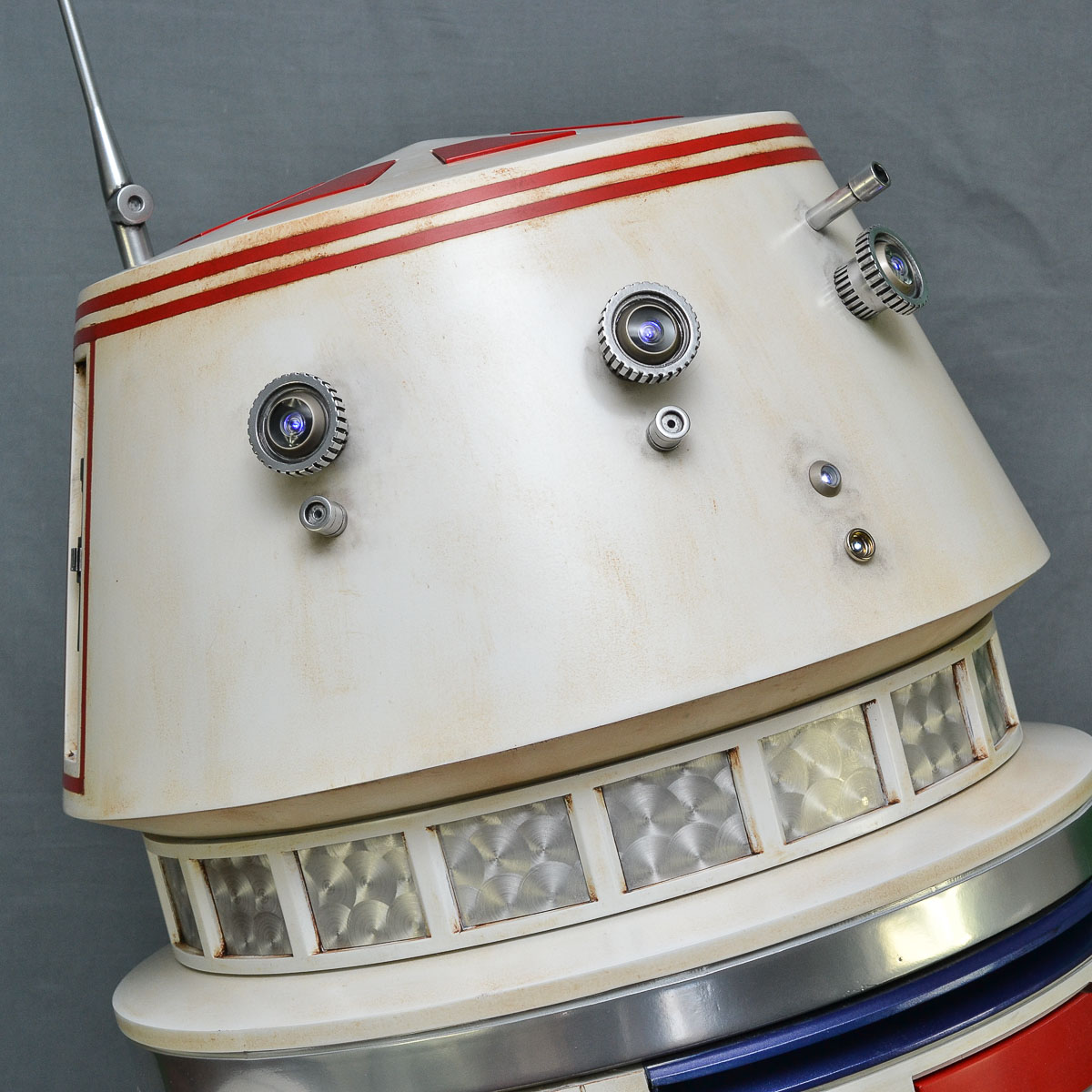
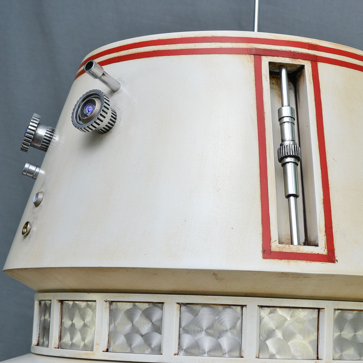
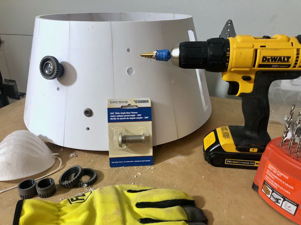
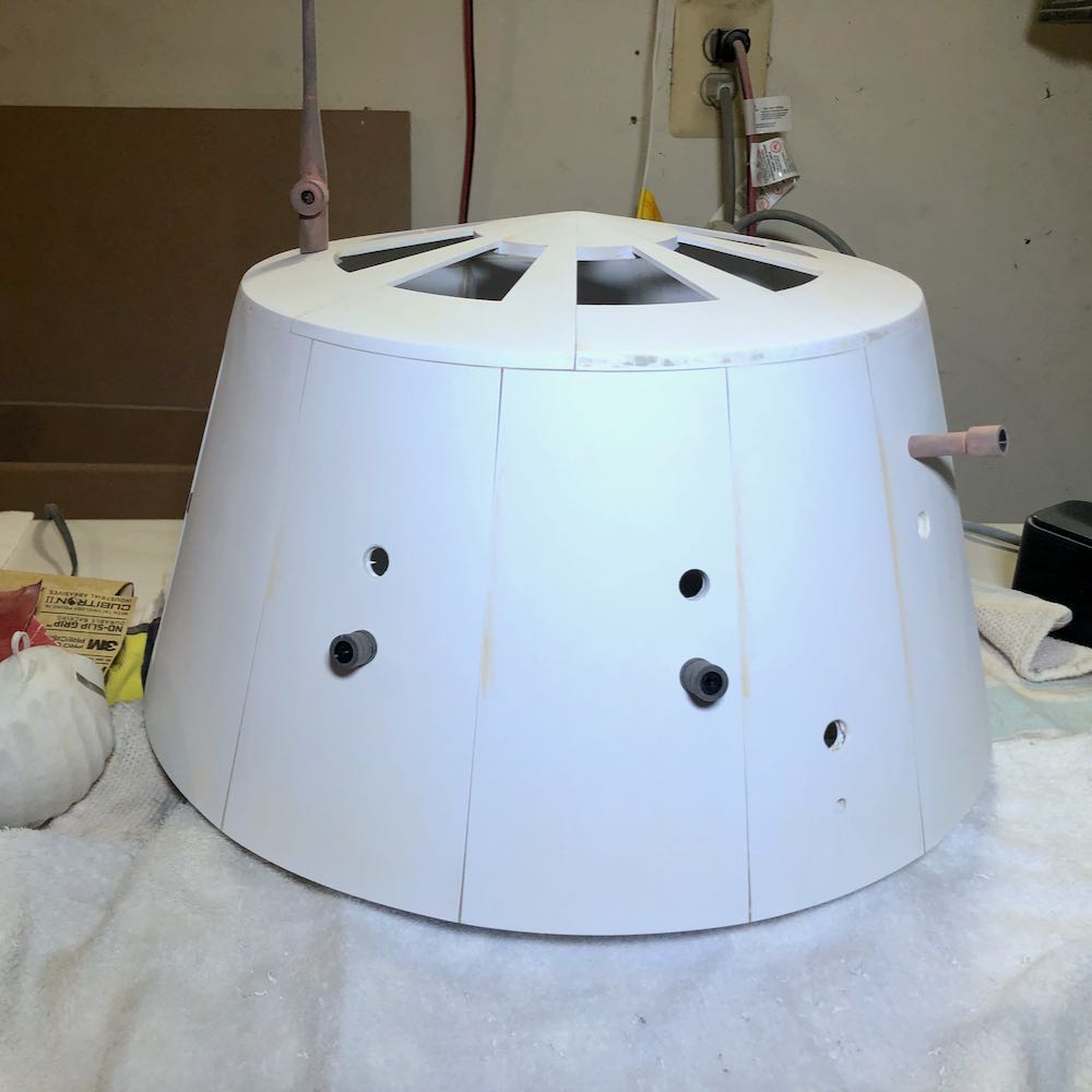
I have seen other R5 builders use door viewer peep holes for eyes. Using a step-up drill bit, I enlarged the holes for the peep-holes. It is best to get the drilling out of the way before painting.
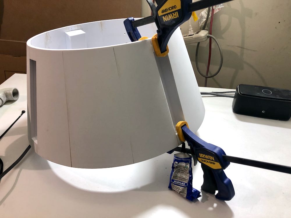
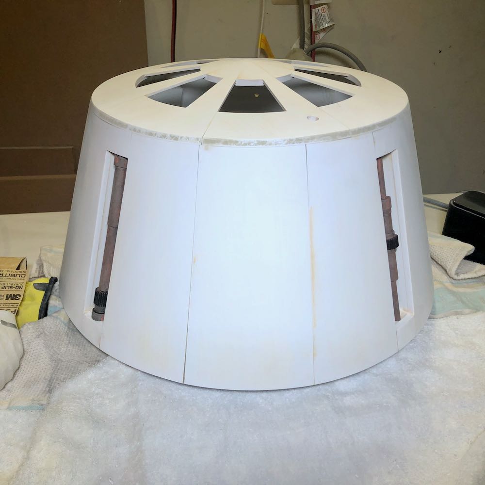
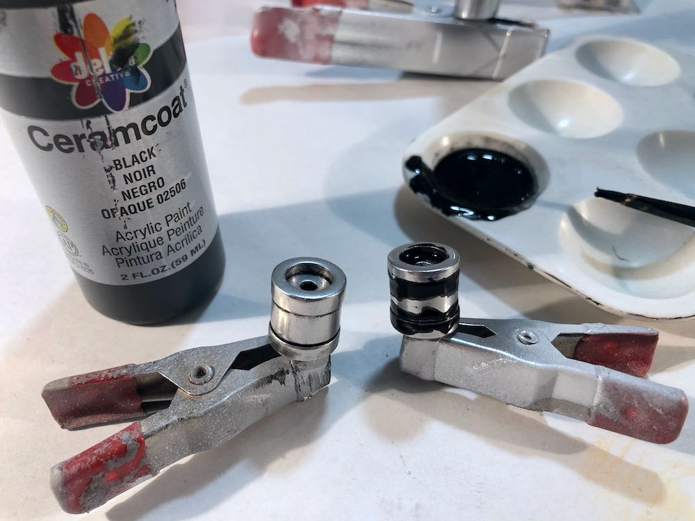
Next, I mounted the rod boxes on the main dome. I used my standard concoction of adhesives, and used clamps to ensure a secure bond.
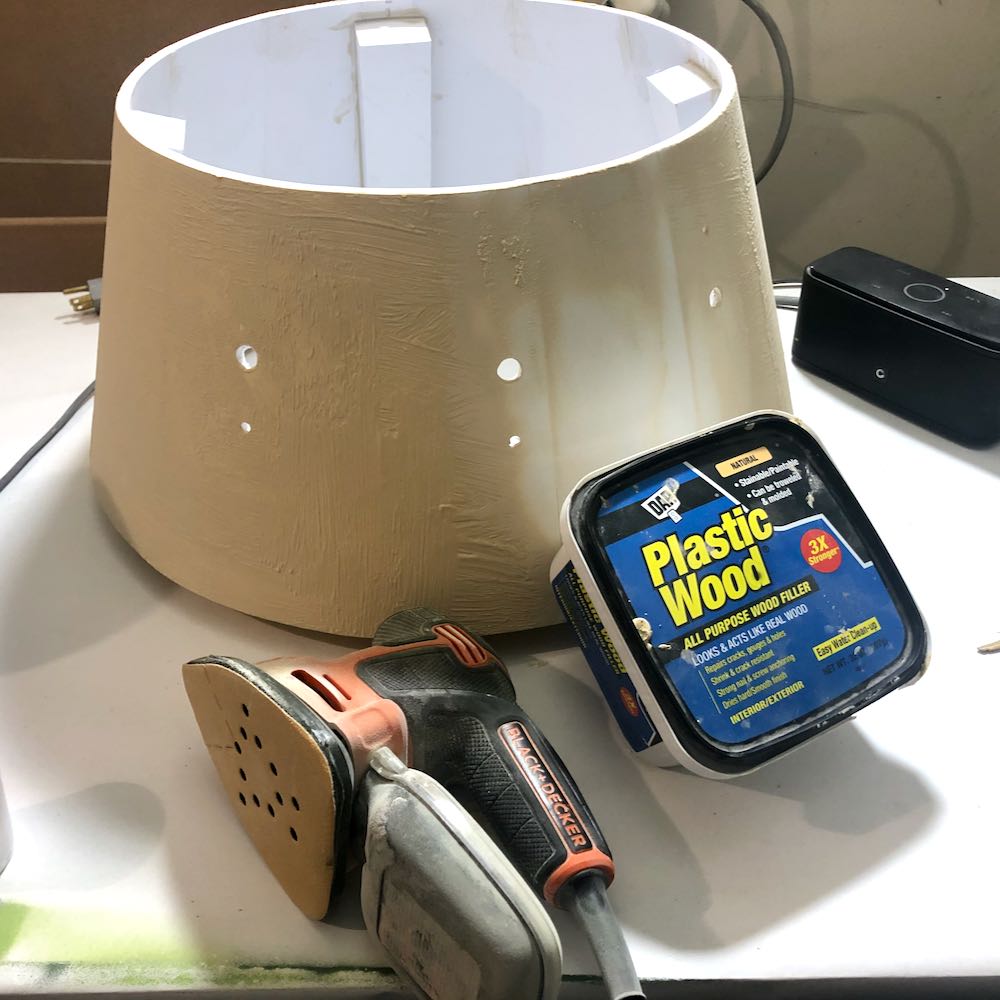
With the main dome now assembled, I used wood filler putty with a dash of water, applied with chip brush to fill any remaining gaps/ridges. After leaving it overnight, I removed it with a mouse sander with a 220 grit pad.
I glued the top of the dome to the main dome with the usual adhesives. Once it was secure, I sanded excess plastic from the top of the dome with a mouse sander. The main gap was filled with epoxy. I sanded past the walls on the dome topper and had to fill in some holes with Bondo 2 part filler.
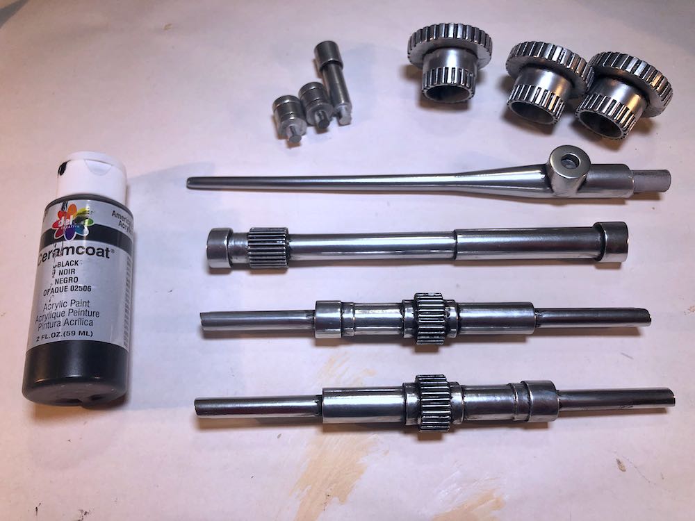
I checked the fitment of the rods in all of the boxes. They did need some minor sanding to fit. If it is snug, don’t force it, it could pop one of your joints. Sand down the rod connections so that they have a comfortable fit.
After checking the rods, check the eye pieces and antenna too. Drill/sand/file to correct for any tight spots.
The rods, antenna, and 3 main eyes required assembly. I used SCIGrip #16 on those items. After they were assembled, they were sanded with 120 grit sandpaper and also sanding twigs for hard-to-reach areas. Bondo Glaze Spot Putty was applied, and sanded off with 220 grit.
Priming
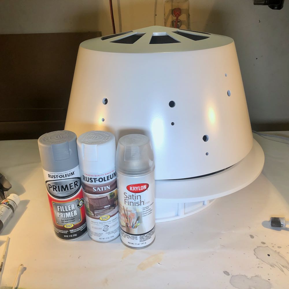
Prior to priming, ALL of the pieces were sanded with 400 grit sandpaper. The pieces were then primed with Rustoleum Filler Primer spray. I sprayed a light first coat, waited 5 minutes, sprayed a 2nd light coat, waited 5 minutes, then sprayed a 3rd coat. Avoid applying this in heavy coats, otherwise the primer will remain tacky. Let it build up slowly. If you see a large gap/ridge, don’t rely on the filler primer. Take a step back and use some putty.
This primer only needs a few hours to dry. Once it was dry, I wet sanded everything with 400 grit sandpaper. Filler primer will:
– fill minor scratches & ridges
– help identify any surface imperfections prior to application of the color coats
– give better top coat adhesion
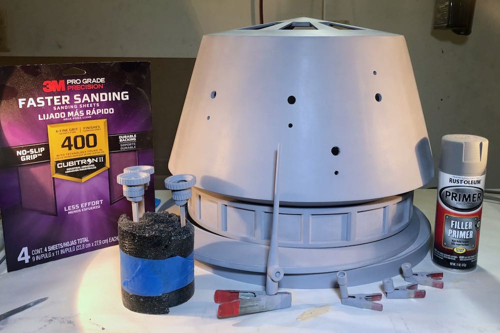
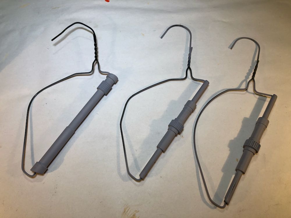
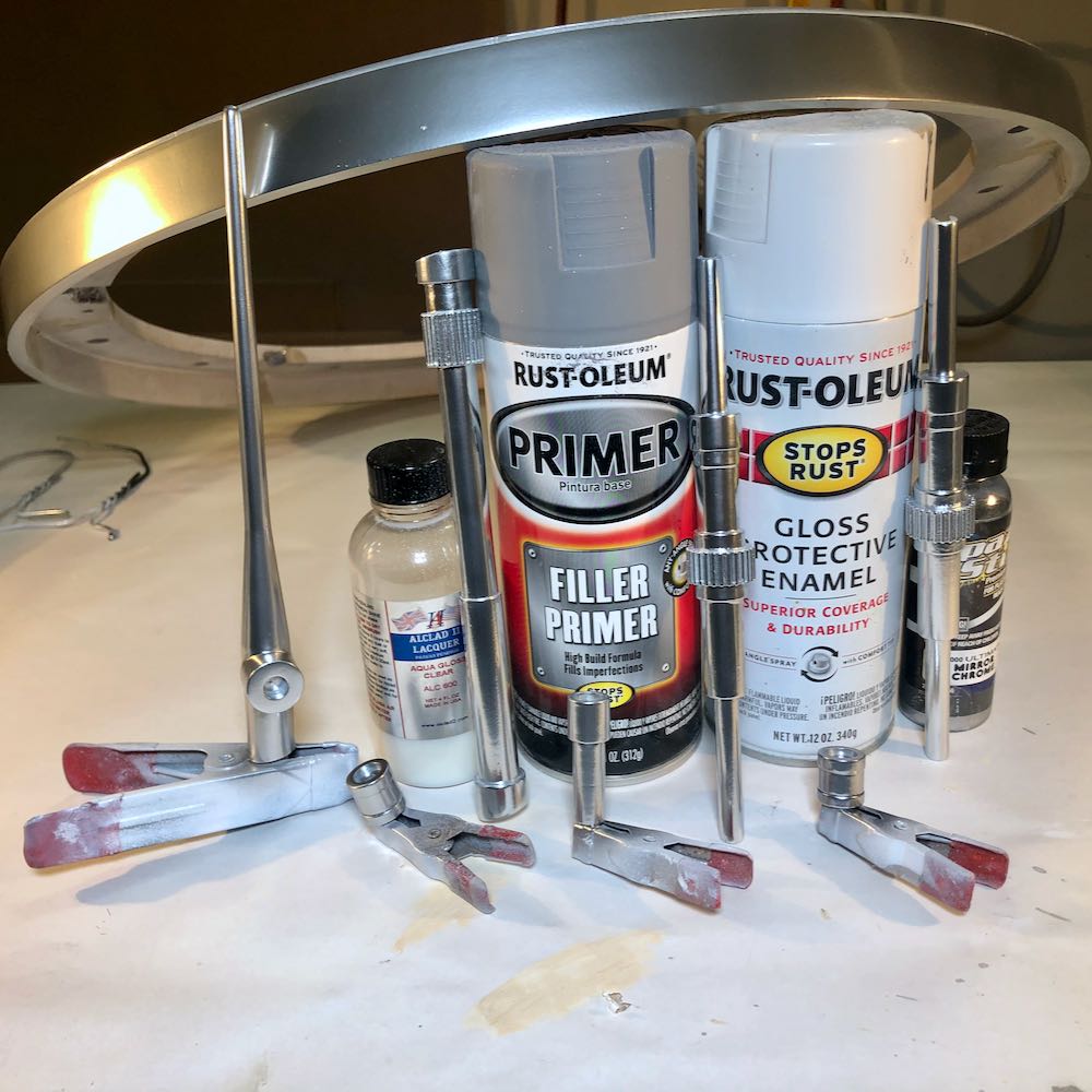
I cut up a few wire hangers to use as holders for the 3 dome rods. They came in handy throughout the painting process.
If you still see some gaps/ridges after priming, apply the appropriate filler, sand it, hit it with a coat of primer, and then wet sand again. I had to go through this step twice. Now is the time to fix imperfections.
Painting
The dome pieces were painted with Rustoleum Satin White. Just to give it a little extra protection, I applied a clear satin top coat. I couldn’t find a satin clear coat by Rustoleum, so I used Krylon Satin Clear. I did not experience any issues with the 2 different brands of paint.
The lower ring, eyes, rods, and antenna were sprayed with 3 coats of Rustoleum Gloss White Enamel Spray. After at least 48 hours of curing time, I used an airbrush to apply Spaz Stix Mirror chrome on the objects. The greeblies should probably not be chrome, they should look more like polished aluminum. Fortunately, the top acrylic clear coat: Alclad Aqua Gloss Clear, will slightly dull the finish, and also apply a much needed layer of protection.
Pinstriping
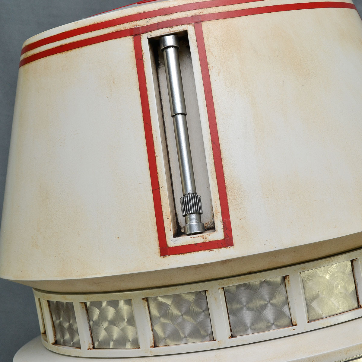
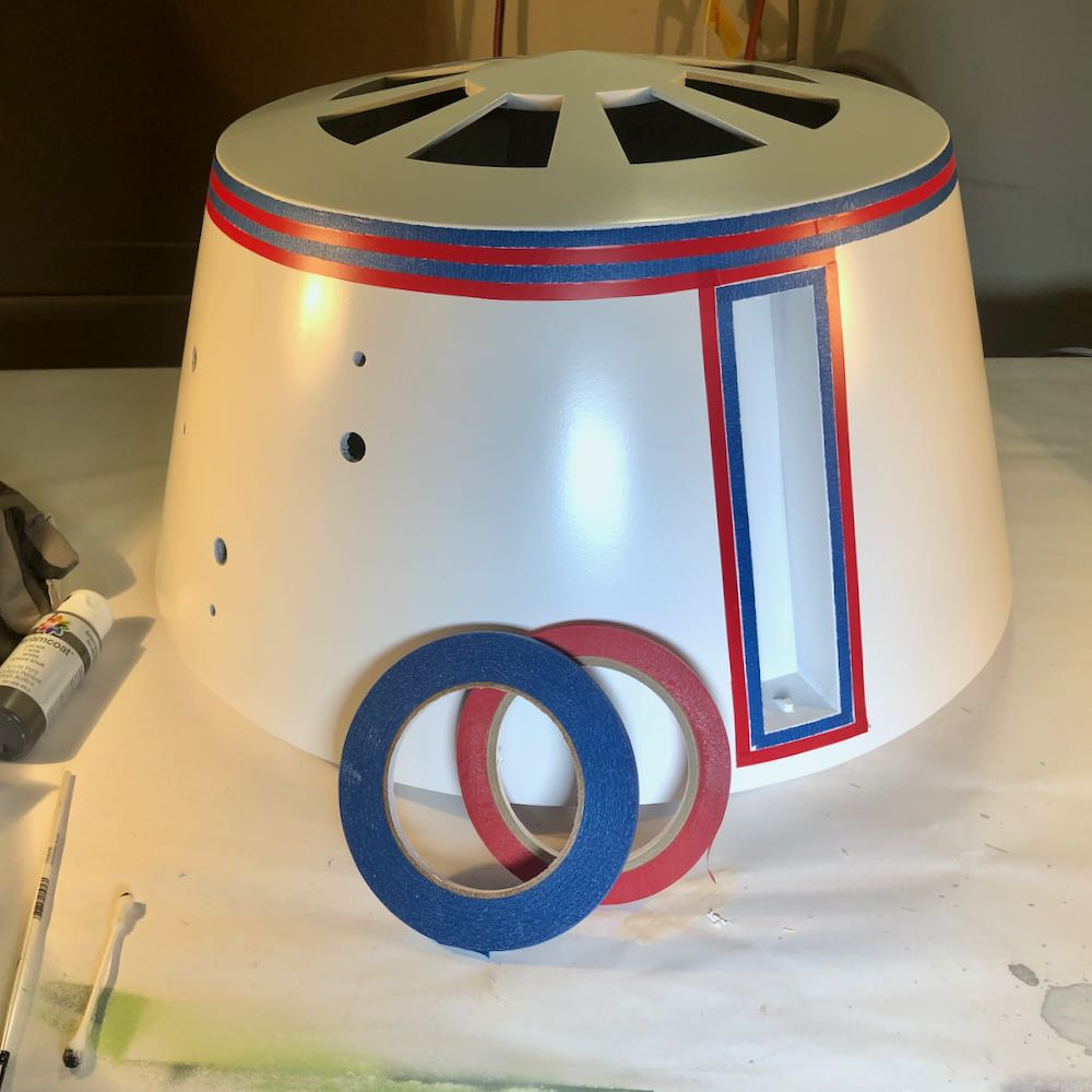
R5-D4 has some beautiful pinstriping around the top dome and rod boxes. I used some 1/4″ red vinyl pinstripe tape from Amazon. I also picked up some 1/4″ painters tape to use as a spacer. An X-acto hobby knife was used to cut the tape.
One thing I forgot to photograph are the top dome red pie panel pieces. I sprayed them with Rustoleum Apple Red Gloss. It was also topped with Krylon Satin Clear.
Weathering
To weather the “metal” pieces, I used black acrylic paint from Michael’s craft store. It was lightly thinned with water. I brushed the black in all of the recessed areas and then after about 2 minutes, lightly wiped it off with a damp paper towel. This left paint in the recessed areas.
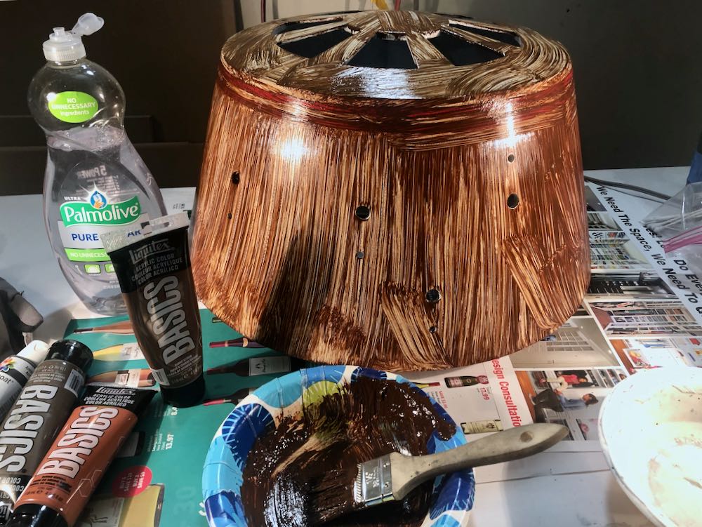
To weather the white dome pieces, I used Liquitex Basics acrylic paint in burnt umber. I squirted a blob out in a paper plate and then applied it everywhere with a 2-inch chip brush. I left it on for about 2 minutes and then used a damp towel to remove it. Enough should stick and give your dome some color. If you leave it on too long, the acrylic dries and it is difficult to remove. You can safely use Windex to remove it. This will not affect the enamel layers below the acrylic.
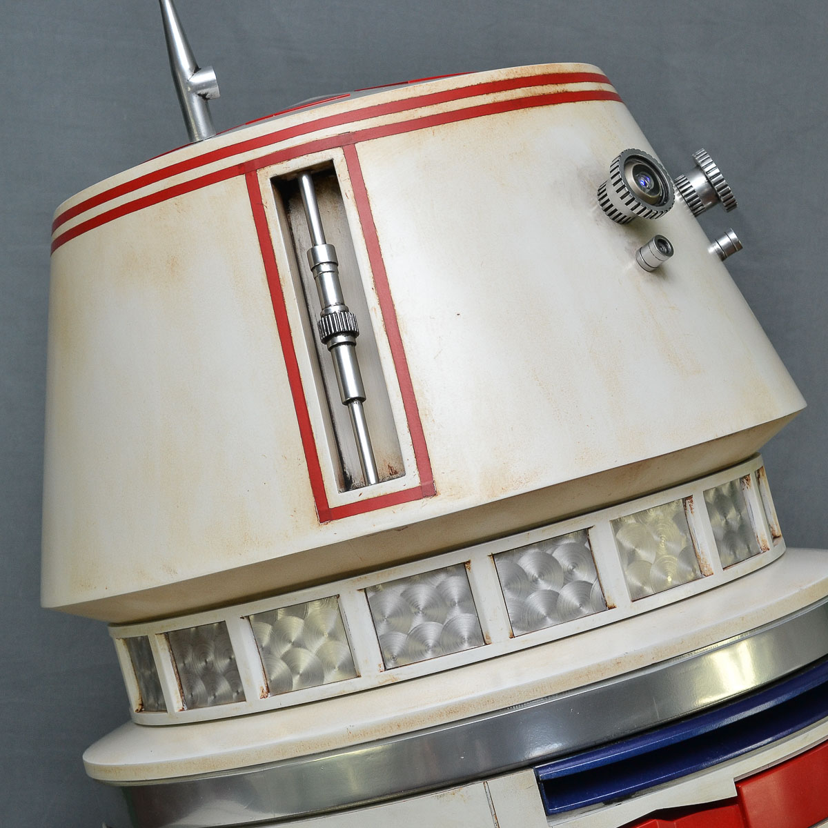
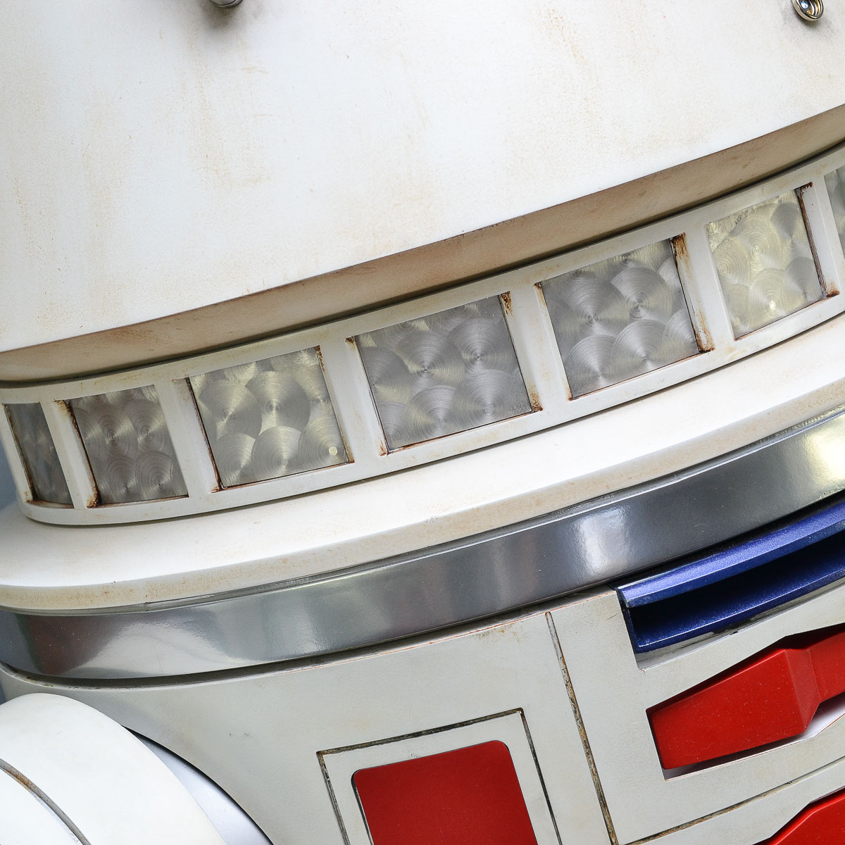
Dome Ladder Panels
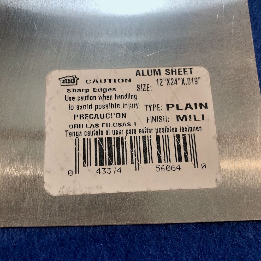
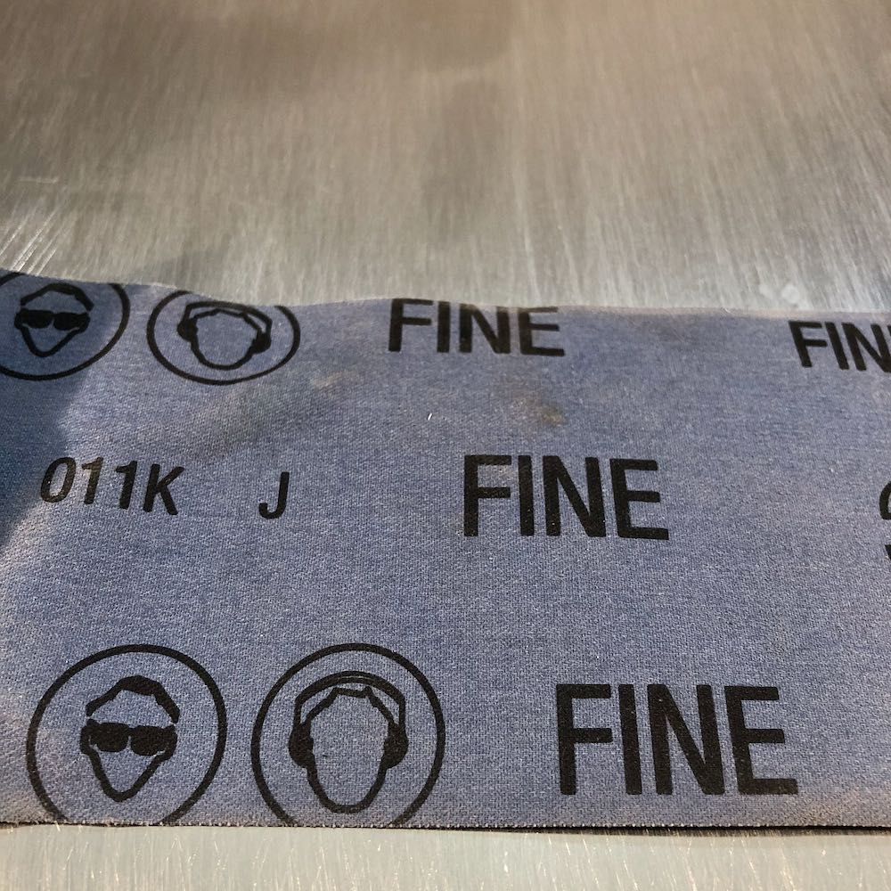
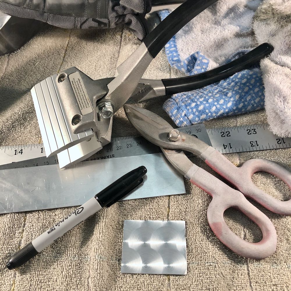
R5’s dome ladder panels appear to be engine turned aluminum sheet. They could also be holographic stickers. I like the look of real metal. I looked for engine turned aluminum online, and it is rather expensive. It was about $70US for a small sheet. I checked online and found 2 great tutorials on YouTube for making engine turned aluminum. The first video is probably the most informative. A grid is drawn on the aluminum, and a drill press is used to hit each intersection of the grid. The second video showed which drill bit bad to use. I picked up a 1 inch disc pad holder and some discs on Amazon for $15US. Home Depot sells 12″ x 24″ x .019″ aluminum sheet for about $10US. I already have an inexpensive drill press from Harbor Freight.
Prior to engine turning, I used some fine emery cloth to sand the sheet. I went back & forth in one direction. Not a circular motion, not up & down…only left & right.
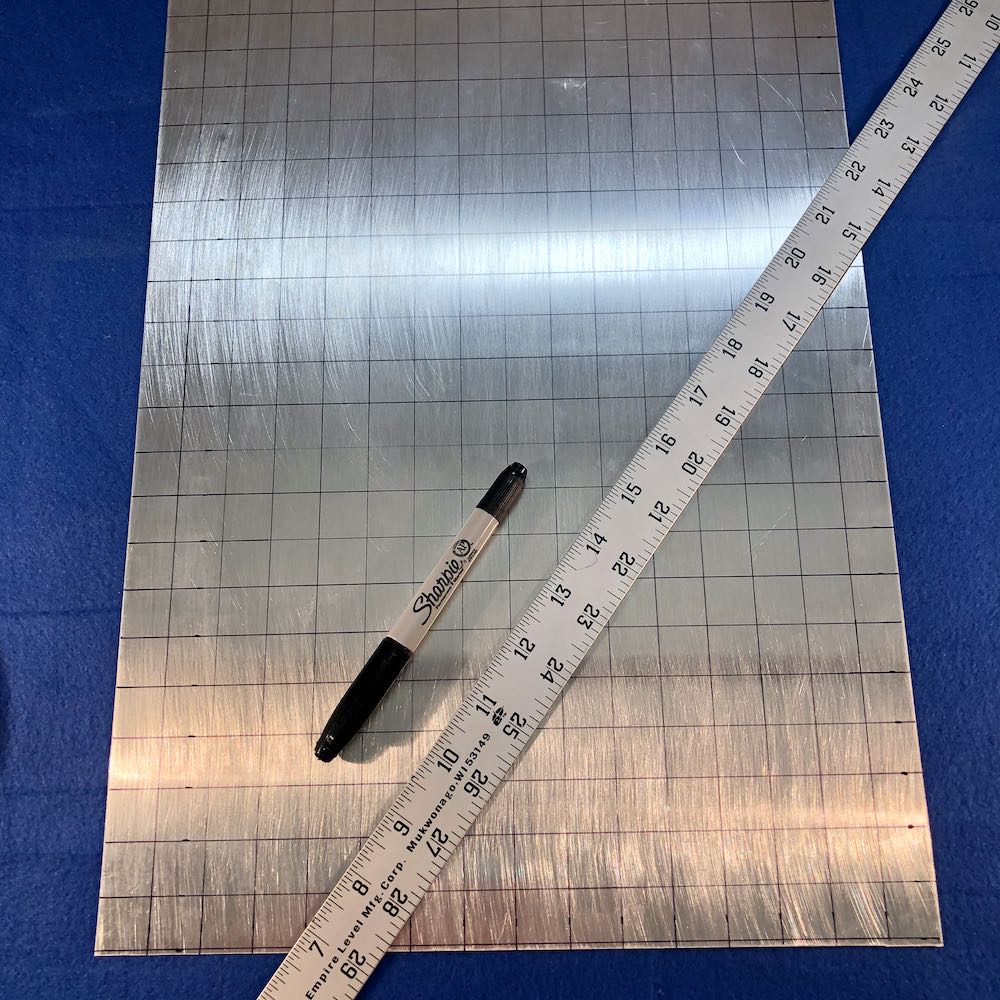
Using a yardstick and a fine tip Sharpie, I drew my grids in 3/4″ intervals. I will be using a 1″ sanding disc, so 3/4″ will provide a nice overlap of circle patterns.
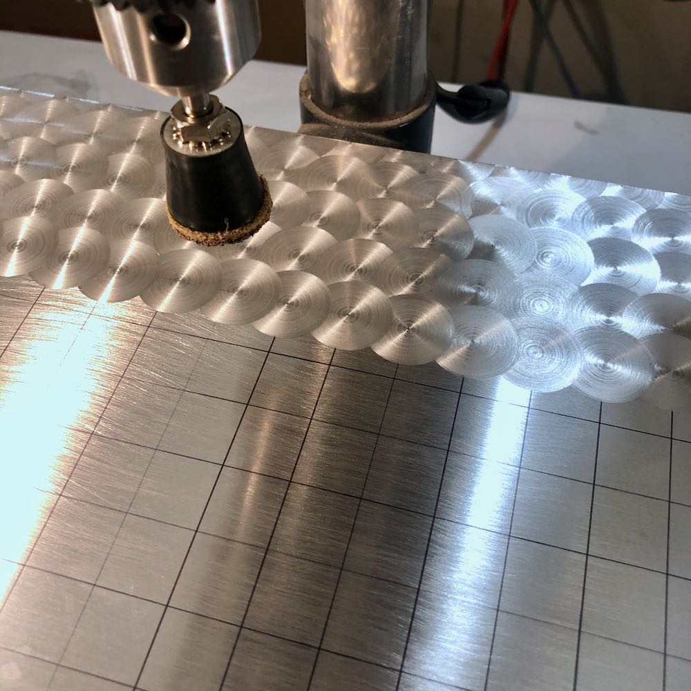
Attach the sanding disc and start drilling! Try to center the drill bit on each crosshair. Watch the video in the link above to get the pattern. Left to right, move down, then go right to left, repeat. After about 5-6 rows, I ran out of room and stopped.
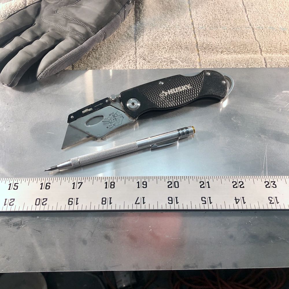
I ran the pattern lengthwise. I cut a long strip that measured about 4.3cm high. For this long strip, I clamped a straightedge (metal yard stick) down on top of the rear of the aluminum, and used a utility knife to make about 5-6 passes. I carefully bent the sheet a few times until it snapped off with a nice clean edge.
On the back of the strip, I drew a line that was 5.2cm long. I cut this with a pair of straight cut tin snips ($6 from Harbor Freight).

The snips may bend the sheet slightly. I used a 3-1/2″ sheet seamer to straighten it back out ($10 from Harbor Freight). You can use anything that you may have on your workbench. I had this seamer left over from my Imperial belt box project.
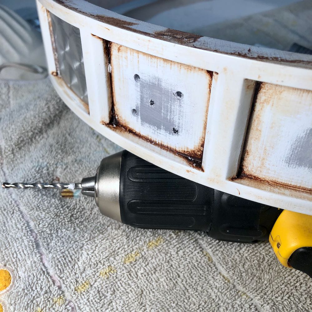
I drilled a few holes in each ladder ring panel to: 1) help me if I ever need to push it out for replacement 2) let some glue seep in there.
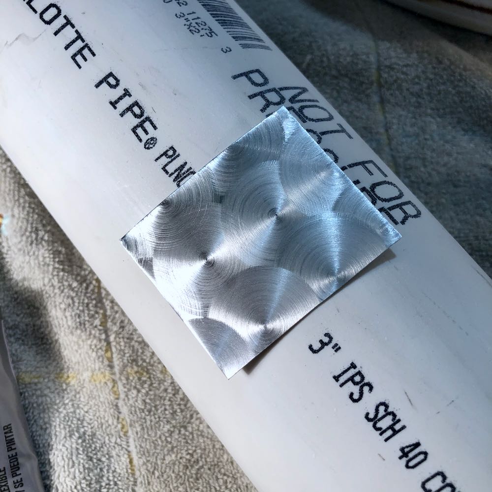
To give the panels a slight bend, I pressed them against some 3″ PVC pipe.
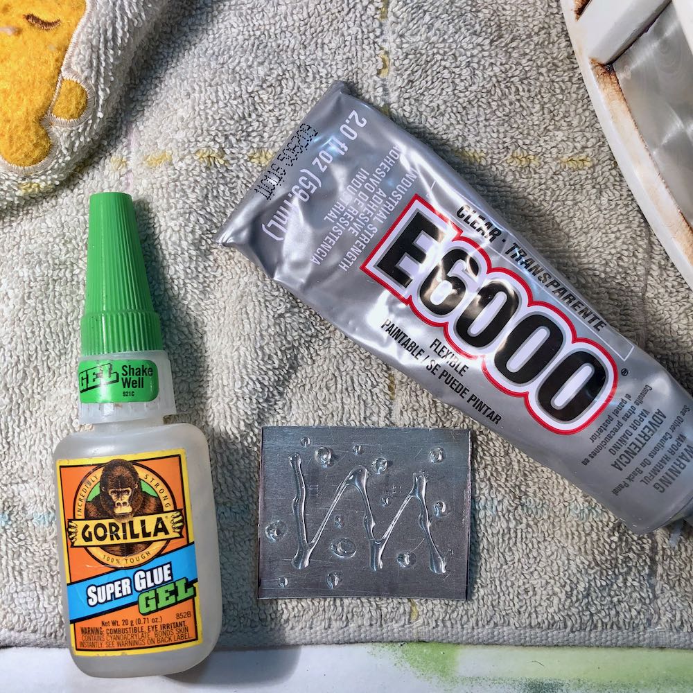
I used some Gorilla Super Glue Gel for a quick bond, and also used some E-6000 adhesive for strength.
Final Assembly
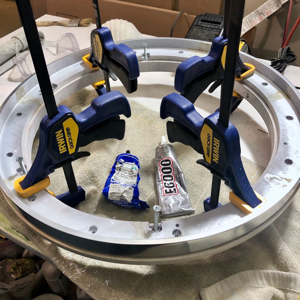
I will start from the bottom and work my way up. I sanded the lower “aluminum” ring connection point with 120 grit sandpaper to remove any paint, and also sanded the ring that sits on top. I used a combination of SCIGrip #16 and E-6000. It was clamped and left for 24 hours.
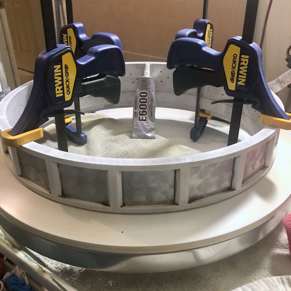
I sanded the connection point of the ring between the lower ring and ladder ring, but there was still quite a bit of paint on there and the connection is a bit narrow. Rather than use SCIGrip, which only fuses acrylics, I opted for E-6000 which secures almost everything. I sanded the paint off as best I could and then applied E-6000 to both rings and clamped for 24 hours.
The main dome was secured to the 3 lower rings the same way: E-6000, clamps, 24 hours.
E-6000 was also used to secure the rods into the rod box notches.
Electronics
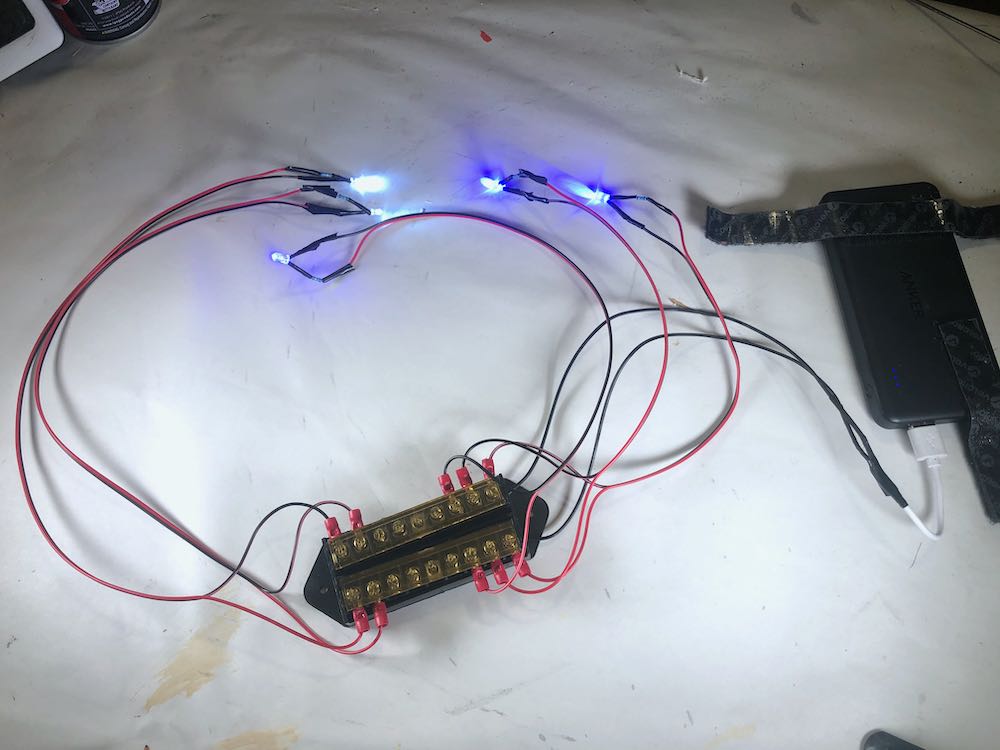
I’m going for a simple LED configuration for R5-D4, no programming/blinking, just 5 lights: 3 blues for the main eyes, and 2 whites for the lower eyes. I could run these lights from my 12V power supply in the astromech’s body, but I have found it is much easier to have a separate power source in the head. It makes assembly a little easier. I will use a 5V phone charging power bank for the LED power supply.
Blue and white LEDs have similar forward voltage, about 3.6V. The power supply is 5V. This is a bit too much for the LEDs, so resistors must be put in place. I suggest using an LED calculator to determine which resistors are needed in your circuit. The resistor you use, will depend upon the LED color, and power supply. I will be using 68ohm resistors for these LEDs. I tested them out on a breadboard prior to assembly.
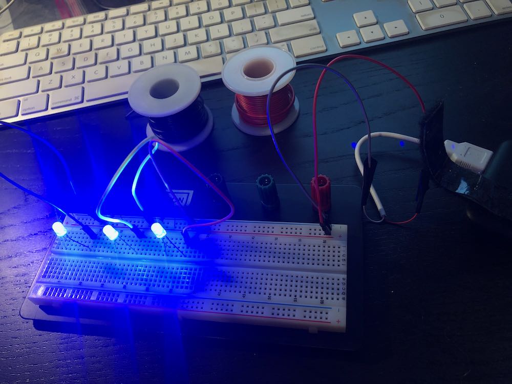
After confirming all of the LEDs were functional, I gathered the materials needed to construct the circuit.
– 5mm Blue LEDs x 3 White LEDs x 2 available from Amazon
– 5V Power Bank available from Amazon
– 68 ohm resistors x 5 available from Amazon
– 22 AWG wire available from Amazon
– 8 way terminal block bus bar available from Amazon
– 22 gauge ring terminal connectors available from Amazon
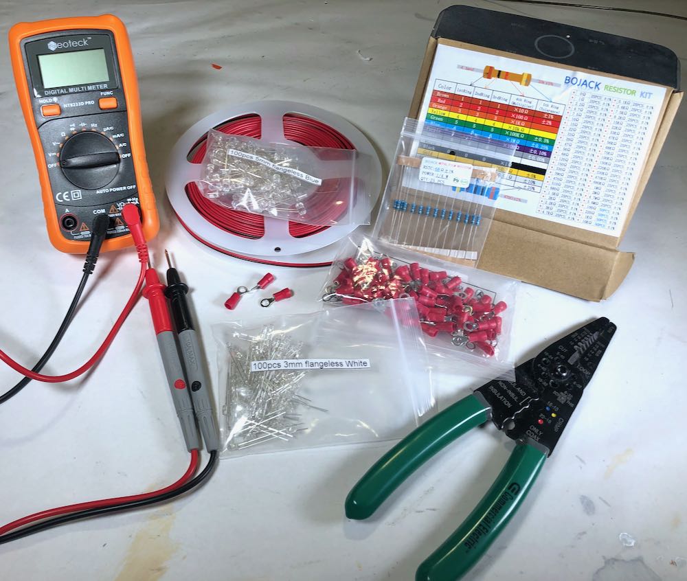
Some tools were needed to complete the assembly:
– soldering iron & solder available from Amazon
– wire stripping and crimping tool available from Amazon
– multimeter was very helpful in checking voltage and resistance, available from Amazon
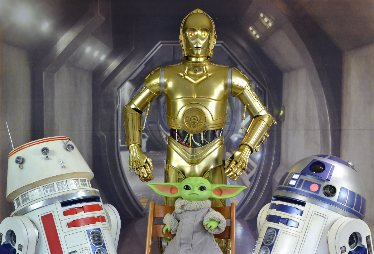
End Results