

Previous Story
HappyTrooper builds an R2 unit
 R2D2, one of the most memorable and beloved characters in the Star Wars universe. Who wouldn’t want their own Astromech droid? While attending different events as a Star Wars costumer, I’ve crossed paths with a few R2 builders. I was intrigued and began researching what it takes to build a droid. If you’ve seen other posts on my blog, you can see that I like to roll up my sleeves and build stuff. R2 seemed like a fun and challenging project to take on. It was just that…especially the challenging part. As a prop/costume builder and plastic modeler, I had some experience with building and painting, however, electronics was a different story. This post details my experiences building an Astromech unit.
First steps
My droid building research quickly took me to astromech.net: the official website of the R2 builders club. You will need to register to view the contents of astromech.net. It can be overwhelming at first, as there are so many different ways to build, control, and drive an R2 unit. Don’t expect to just jump in and start building. Research is key. With a little digging, you can find free blueprints, free 3D print files, and lots of other helpful information to help you construct an R2 unit. R2 can be built using: wood, plastic (sheet styrene and/or 3D print filament), and/or aluminum. The factors that I considered for choosing a building material were:
– cost: I wanted to have a screen accurate droid, without breaking the bank
– weight and the ability to disassemble: I live in a townhome. In order to take R2 to events, I need to have the ability to disassemble and carry him between locations. I also drive a hatchback, so carrying a fully assembled droid would be a challenge. I needed to be able to lift R2 by myself.
Taking these factors into consideration, I decided on a styrene droid. While its not the cheapest option, it is also not the most expensive. Using styrene fit my budget, kept the weight manageable, and allowed me to disassemble and re-assemble R2 in about 15 minutes.
In January of 2017, I committed to building an astromech droid, and placed an order with Media Conversions, an individual that provides CNC router cut R2 bodies, shoulder hubs, legs, and feet (no dome). There is a waiting list, Media Conversions sends orders off to the styrene sheet provider and CNC cutter a few times per year. I was on the waiting list for about 7 months. Media Conversions kept me updated throughout the waiting period.
What did I do while I waited for parts?
Media conversions offers the main body components, but the dome, electronics, and all of R2’s greeblies (decorations) were still needed. There is a vendor on astromech.net that offers a sytrene dome kit and an aluminum dome kit. In order to view those links, you will need to be a registered member at Astromech.net. I weighed the options between the domes. In the end, I chose a styrene dome, because it was a little less expensive, and I am comfortable working with plastic. If the dome were to get scratched or damaged, I would be able to patch it up and repaint it. The downside to a styrene dome is that it is very difficult to get a realistic metal finish. You can have a styrene body and an aluminum dome. I may upgrade to an aluminum dome in the future…for now, I have a styrene dome, and I am happy with it. The vendor typically has domes ready for shipment. I had mine about 1 or 2 days after payment. Super fast shipping. In addition to the dome, this vendor also offers a rockler bearing that the dome attaches too. Its like a lazy susan. I recommend picking this component up from the same vendor, as it is already pre-drilled.
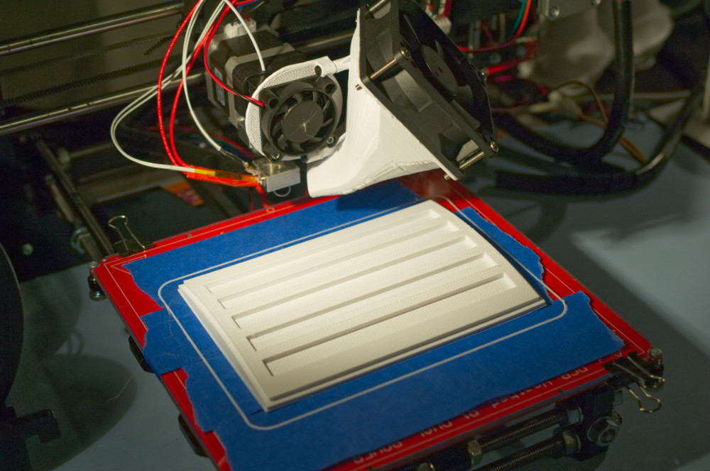
R2 has a ton of little decorations on him, such as vents, utility arms, data port, boosters, pistons, holo projectors, etc. There are vendors that sell these items in aluminum (very realistic, but can be expensive), and also in resin. I checked a few of the resin parts manufacturers online, and they do offer beautiful parts, however, the cost was starting to add up. I saw that astromech.net had ALL of the greeblies available for 3D printing. One problem…no 3D printer…so I bought one. I purchased a DIY Prusa 3D printer. It cost me 1/2 of what it would cost to purchase all of the resin greeblies, and I had a 3D printer at the end of the project. Not to mention, if I break/lose a part, I can 3D print another one. There was definitely a lot of trial and error with the 3D printer. I had no experience. After a few weeks, I was able to print some R2 parts. Be ready for some failures on the 3D printer, it takes a bit of tuning to get things dialed in correctly.
3D printing
Astromech.net has a section with all of the 3D printed parts, you can find it here. Because I had the dome in hand, I printed out R2’s eye, the holo projector components x 3, and the logic display bezels first. These items will be handy to have once you begin constructing the dome, as holes will need to be drilled into the dome to accommodate the 3D printed parts.
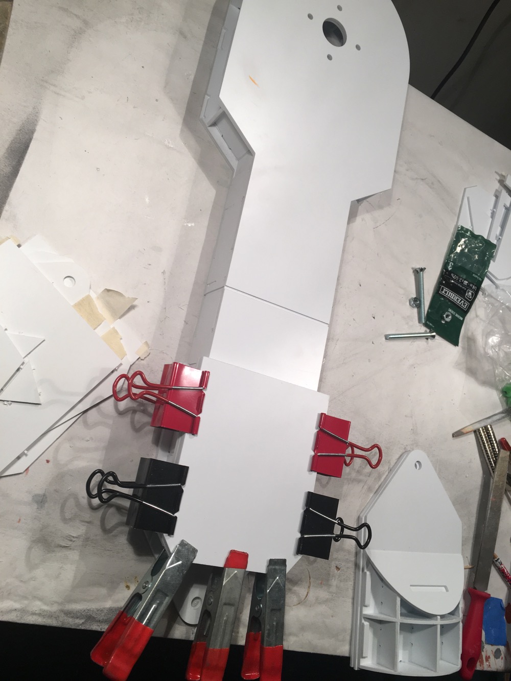
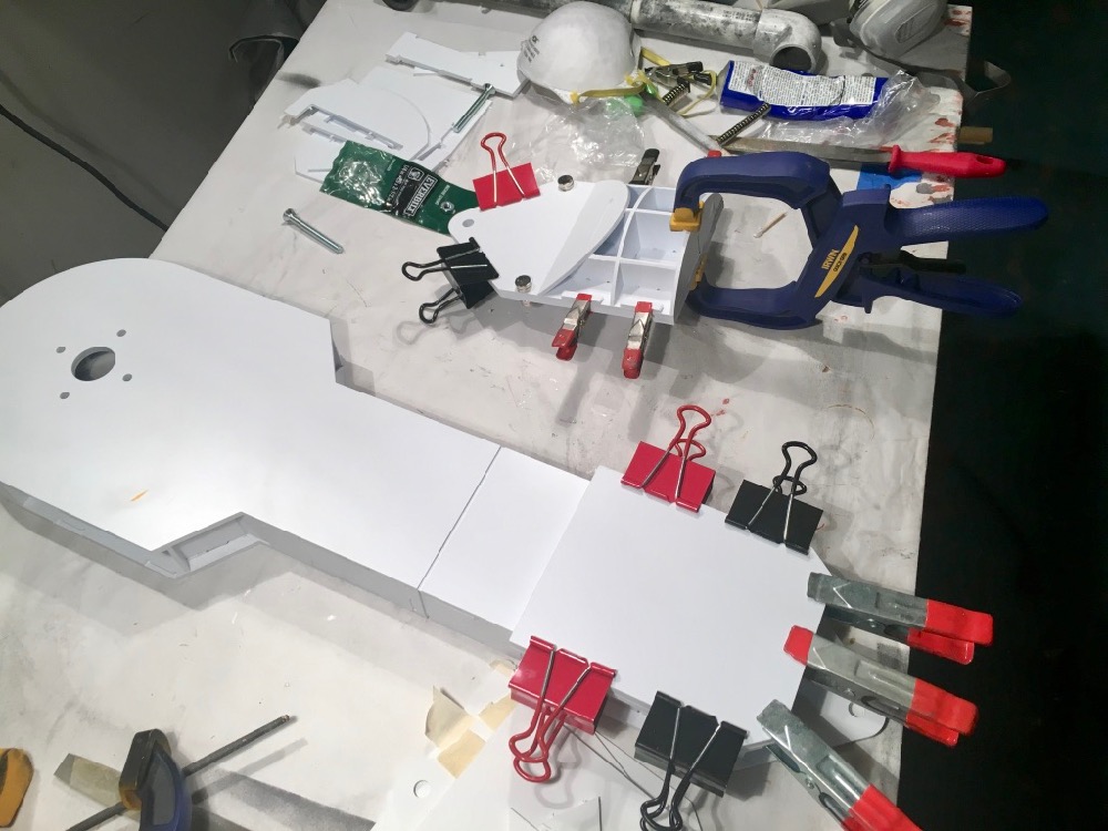
Styrene dome construction
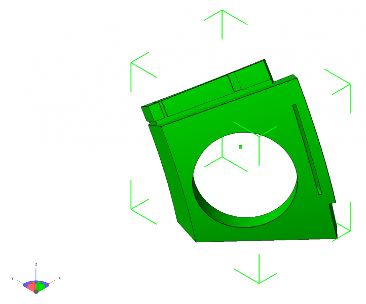
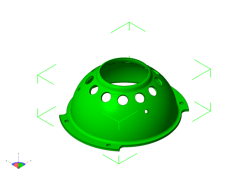
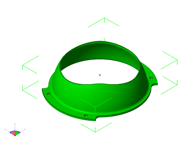
The styrene dome comes in 3 pieces: the inner dome, the outer dome, and the lower support ring. Please note, the styrene dome does not come with instructions. I had to rely heavily on astromech.net builder logs to get me through the process.
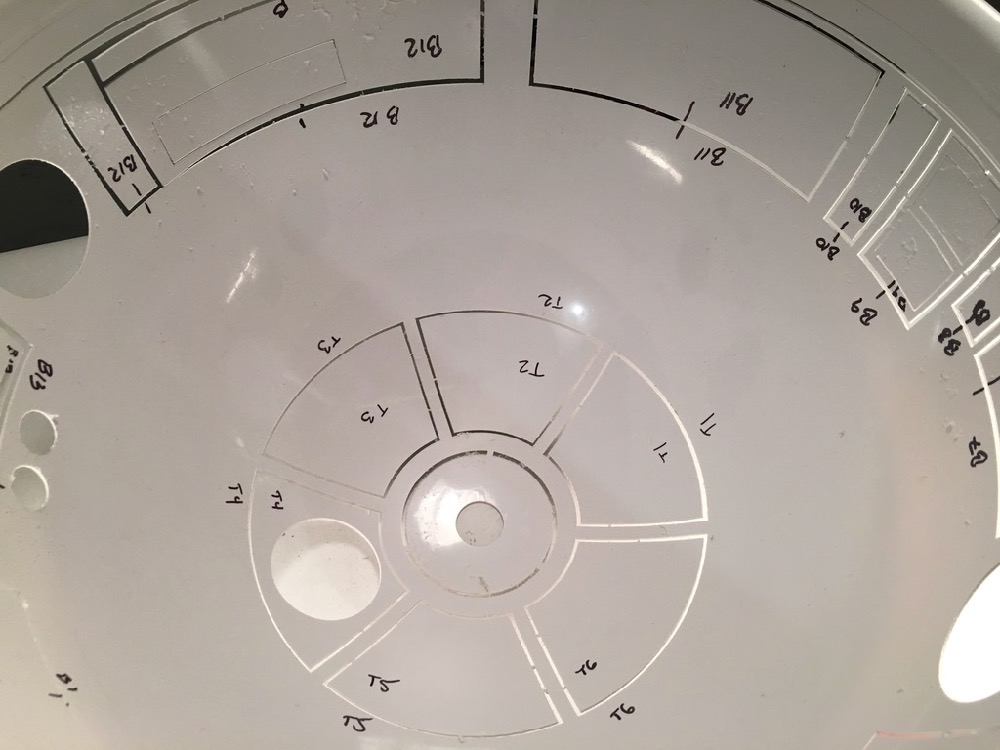
While all of the panels are intact on the outer dome, now is the time to label each panel inside of the outer dome.
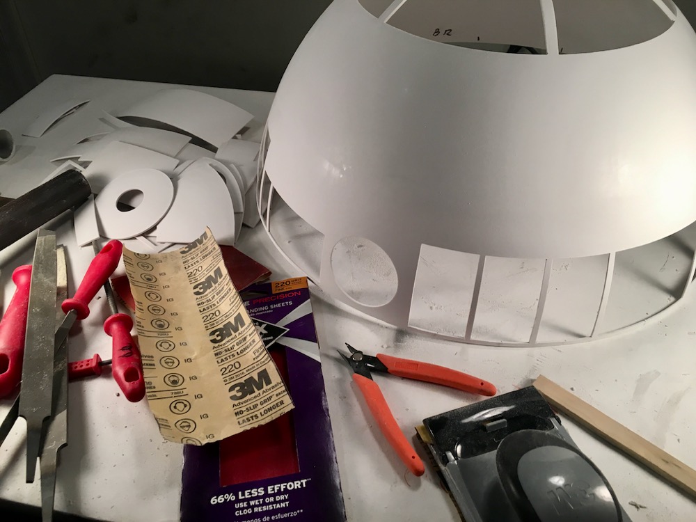
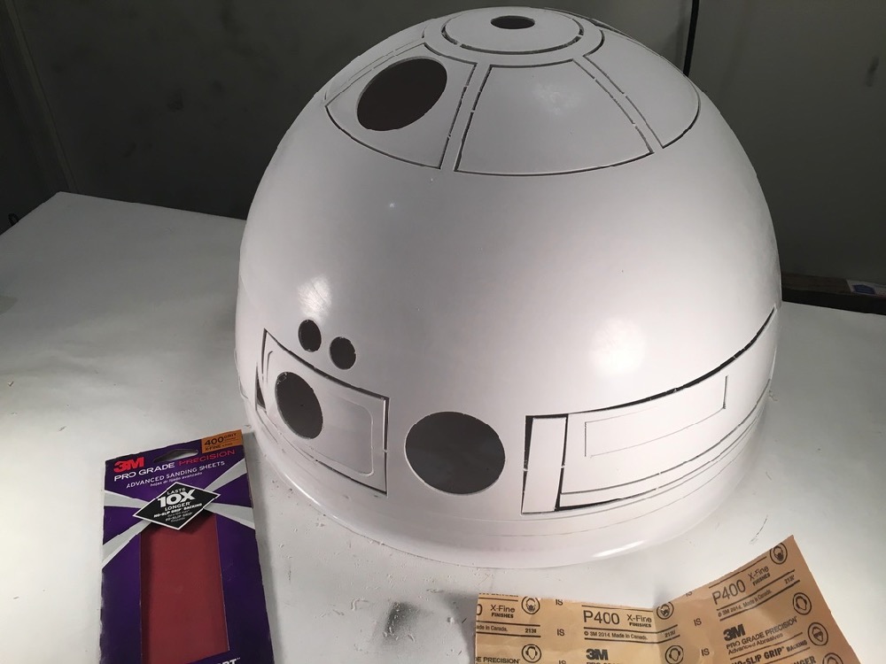
After labeling, I clipped out the panels using a plastic sprue cutter. I then sanded excess plastic from the panels using files and 220 grit sandpaper.
Next, I sanded both of the domes, the panels, and rings with 400 grit sandpaper to give the spray primer something to bite into.
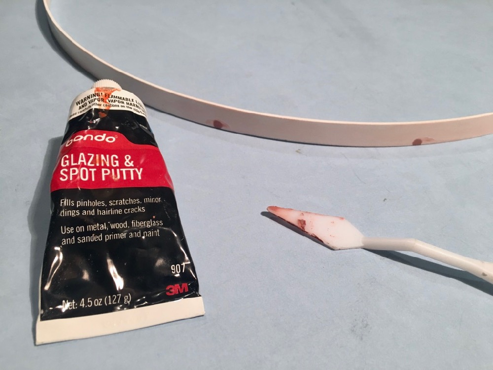
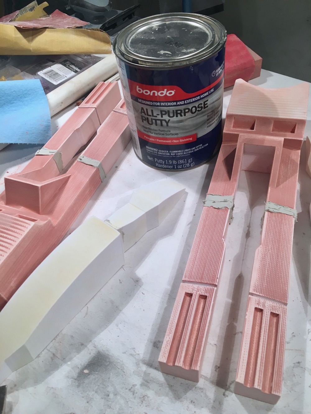
Because this is plastic, you may notice some imperfections, like divots. Now is the time to fill those in with filler. Pinholes and scratches can be patched up with one part filler like Bondo glaze putty.
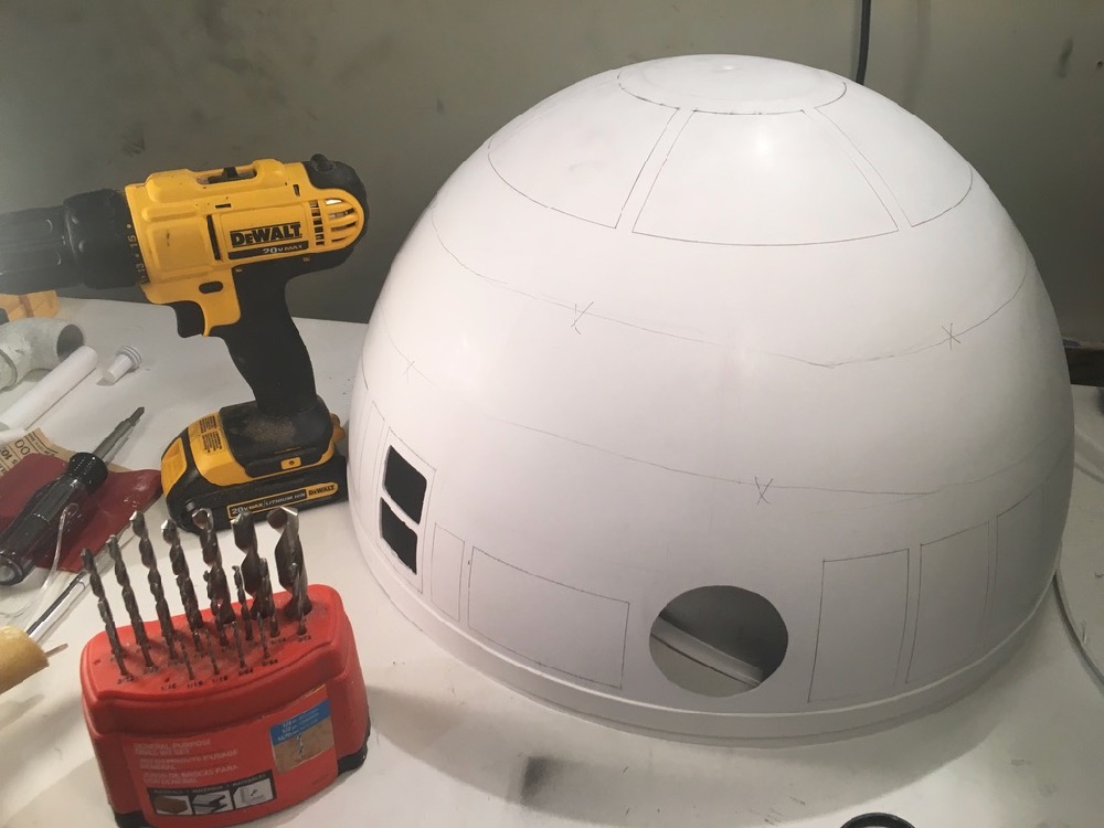
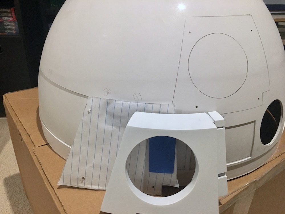
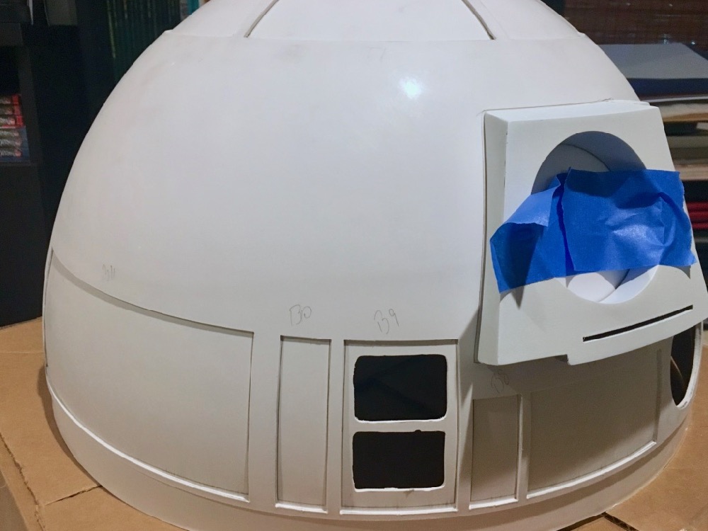
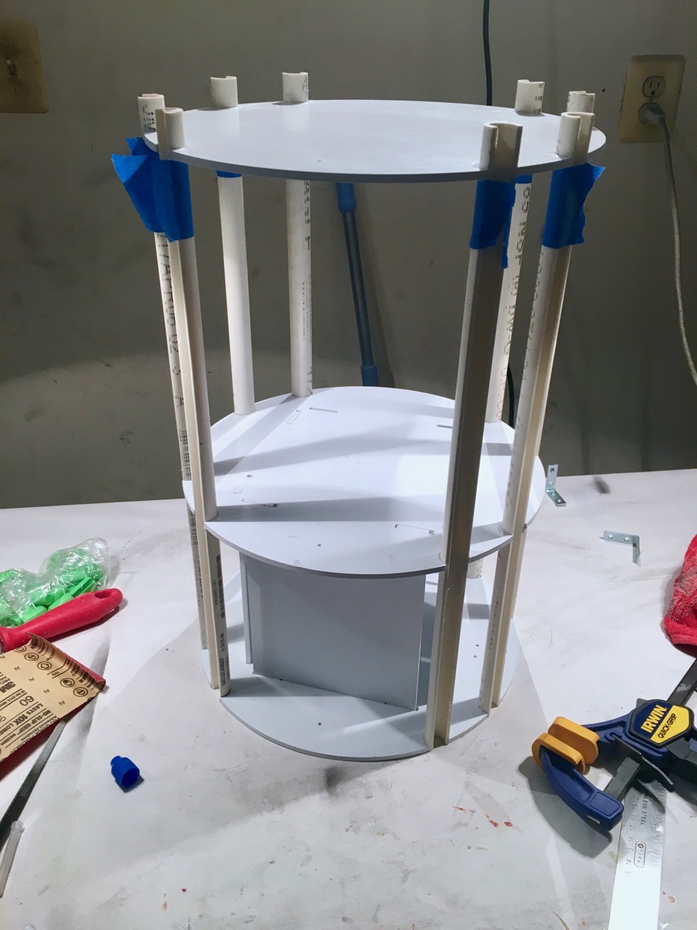
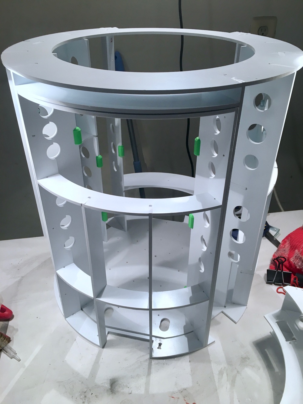
I then worked on alignment of the inner and outer domes, as well as placement of the 3D printed accessories. Additional holes will need to be drilled with a rotary tool to accommodate the holo projectors and logic displays. The outer dome is a VERY tight fit when it is placed on top of the inner dome. I was able to work mine on, & marked the position witha pencil. I did read about other styrene builders cutting their inner domes, as most of it is not seen because it is covered by the outer dome.
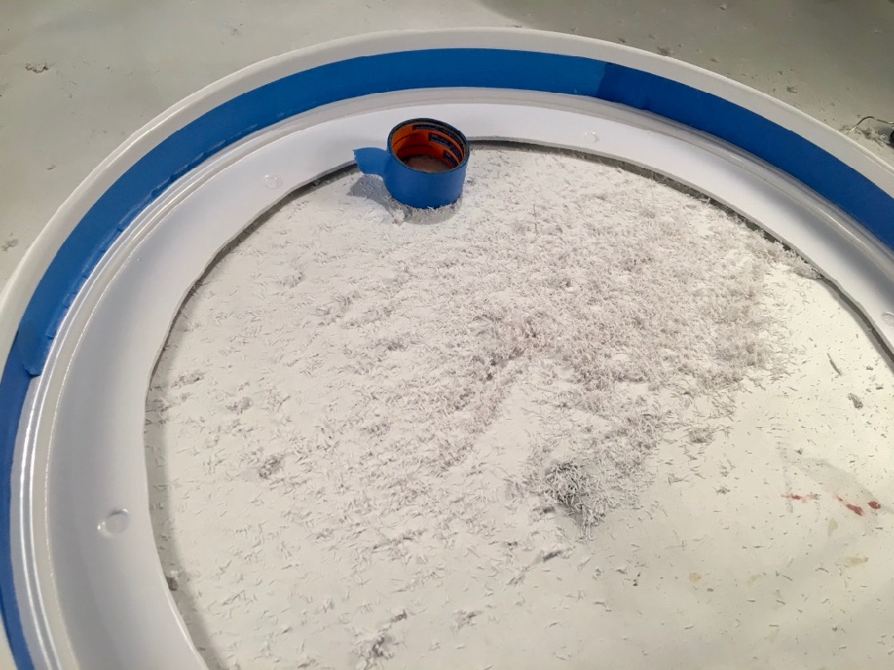
The lower support ring will also need to be trimmed. The middle “filler” will need to be removed. The bottom edge will also need to be trimmed.
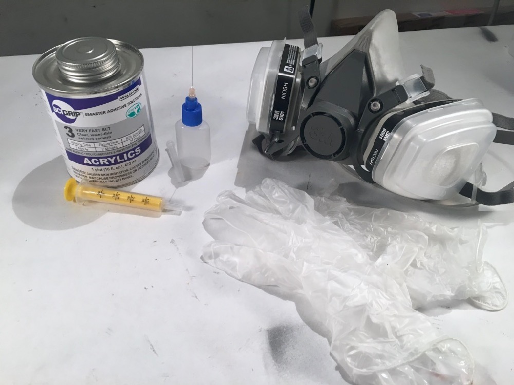
Once everything is in place, its time to secure the 2 domes. Some solvent, along with the necessary precautions, will fuse the 2 domes together. Per recommended practices on the astromech.net forums, I drilled some holes on the inner dome to allow the solvent to flow through.
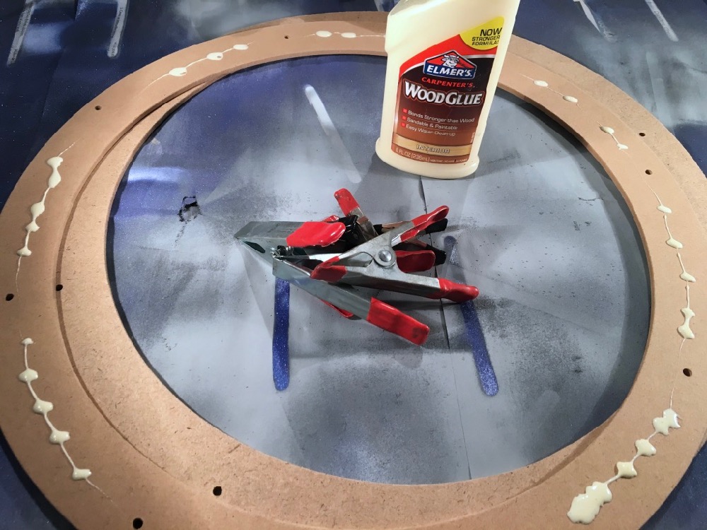
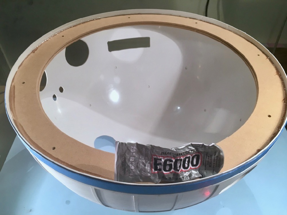
I used 2 floral rings from Michael’s Craft Store for mounting to the “lazy susan”. They were glued together with wood glue. The outside of the rings needed to be trimmed a tad to fit inside of R2’s dome.
Styrene dome cosmetics and painting
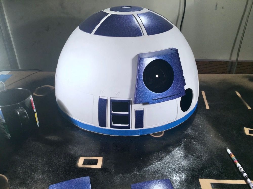
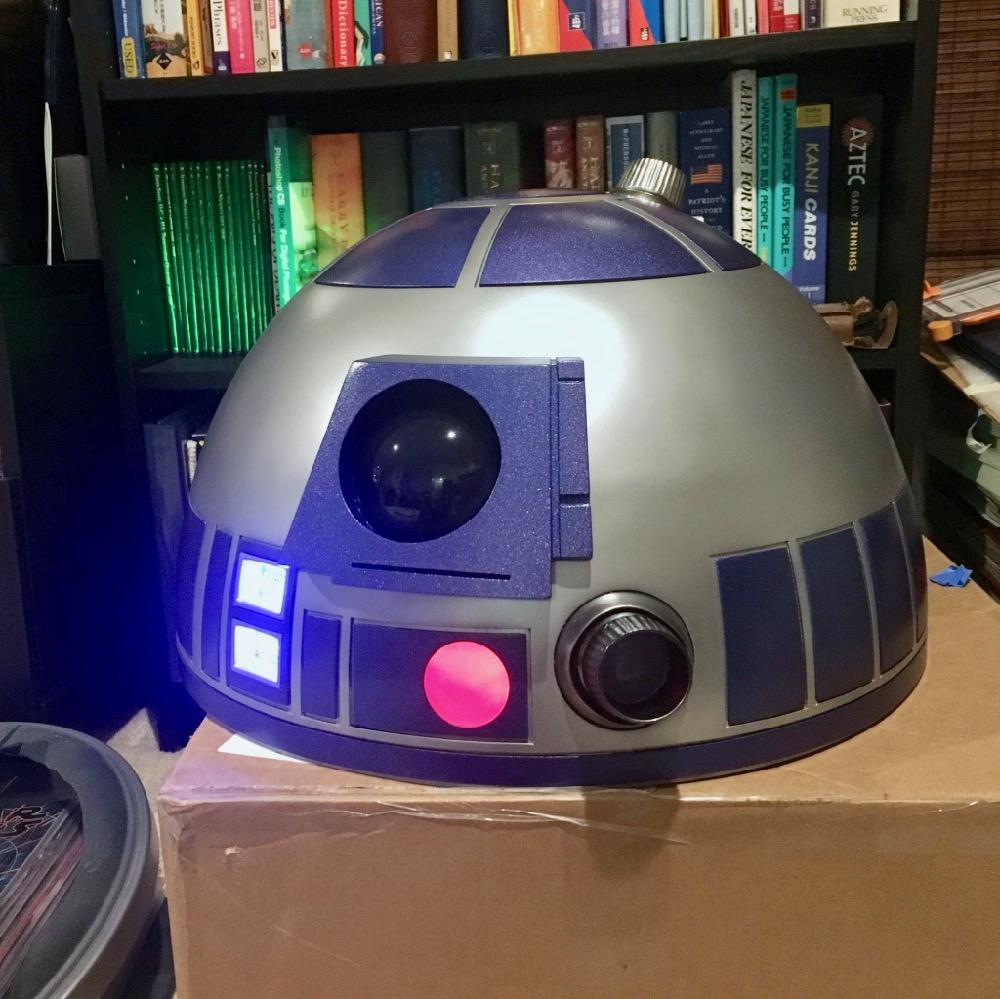
R2’s “eye” is probably one of his most prominent features. I 3D printed this piece, it came out…well…it was the right shape. It definitely wasn’t smooth enough and needed some finishing. If you have 3D printed before, you know that no matter how good your printer is, you’ll probably have some ridges in your print. I used Bondo spot glaze putty to fill in the ridges, and then sanded the crap out of the eye. I started with 100 grit to take the ridges down, then followed up with 220 grit, and finally, 400 grit. I did have to re-apply spot filler in some places throughout the sanding process. This took a lot of work to get a nice finished piece, it was worth it in the end. Because the eye was white with flecks of red from the spot putty, I chose to start the priming process with gray primer. I did this on all the dome panels too because I wanted color uniformity. To make the “blurple” pop a little more, I applied white primer next.
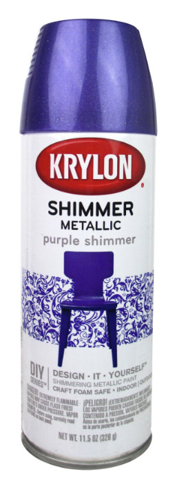
I know some builders use a single color for blurple, I ended up using 2 different kinds of spray. Rustoleum Metallic Blue, followed by a dusting of Krylon Shimmer Metallic Purple.
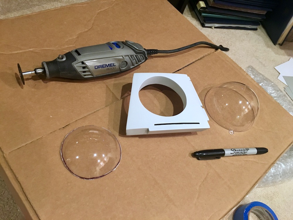
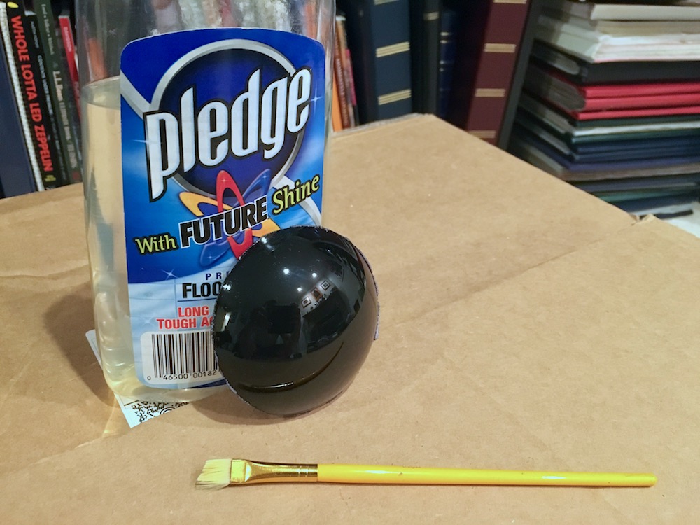
For the actual eye, I purchased some 100mm plastic Christmas ornament orbs from Amazon and cut them with a rotary tool. I painted the inside of the eye with black spray paint, and then covered the outside with a layer of Pledge/Future floor wax, using a brush, to fill in any imperfections on the orb, and give it shine/protection.
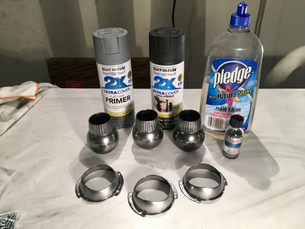
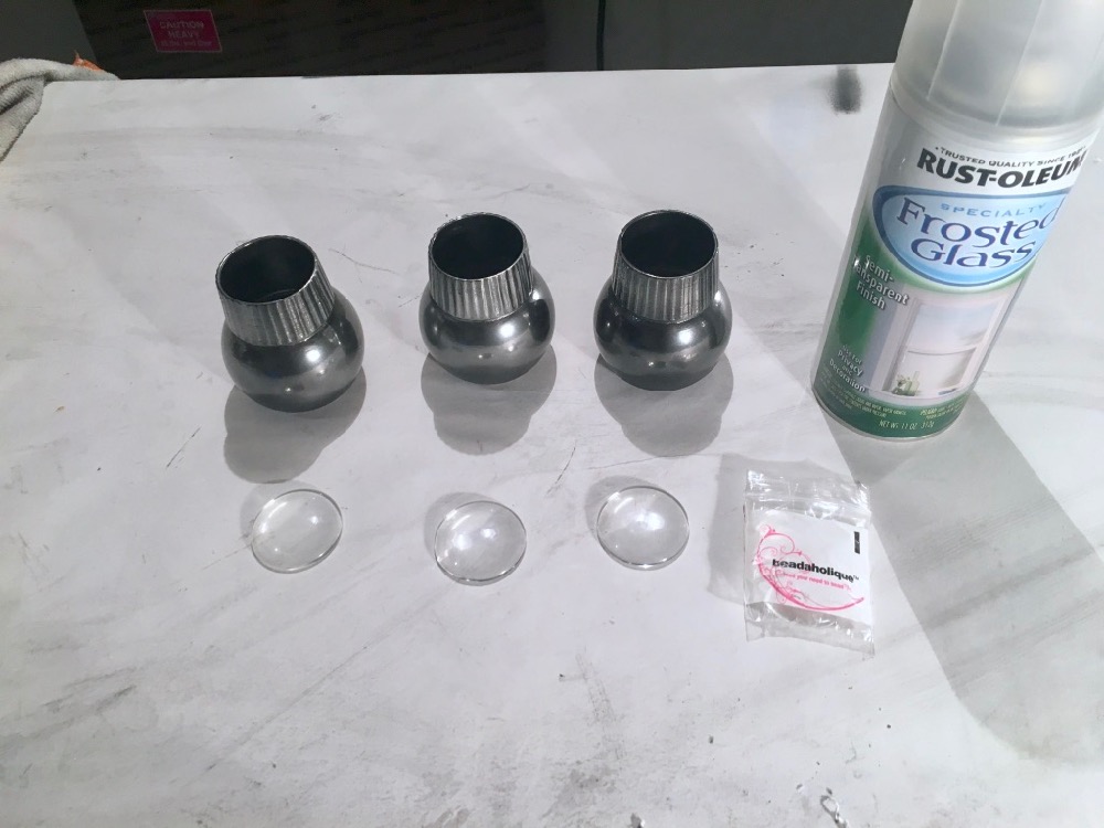
For R2’s holo projectors and logic display bezels, I wanted a little contrast…so it didn’t match the dome. I primed all of the parts, sprayed them flat black, and then applied Future/Pledge to give it a gloss finish. I suppose one could just hit it with black gloss spray too. After all of that cured, I applied Alclad II in Chrome via airbrush.
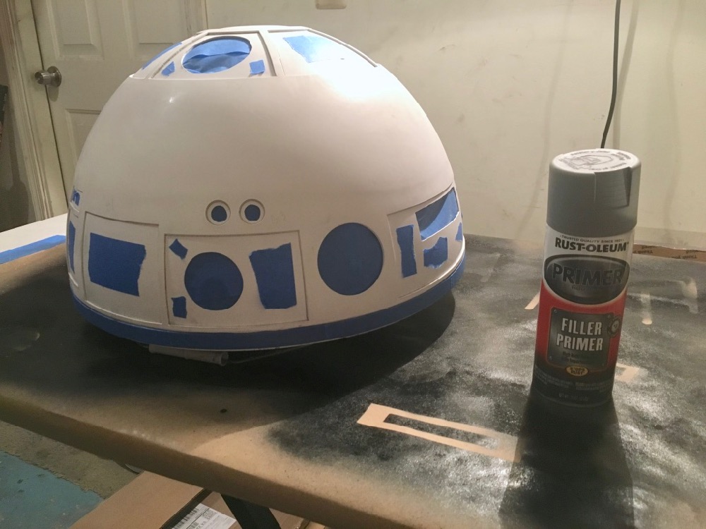
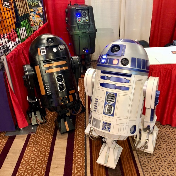
For R2’s dome, I applied filler primer, and then wet-sanded it down with 800 grit sandpaper. I wiped it down with alcohol soaked on a microfiber towel, followed by a tack cloth. I then used the airbrush again to apply Alclad II in Aluminum. In the 2nd photo below, you can see the variation between the aluminum finish on the dome, and the chrome finish on the holo projector.
For R2’s holo projector lenses, I purchased 3 x 1-1/2″ (38mm) glass cabouchons from Amazon. They fit perfectly inside. I sprayed them with frost spray so that they were not transparent.
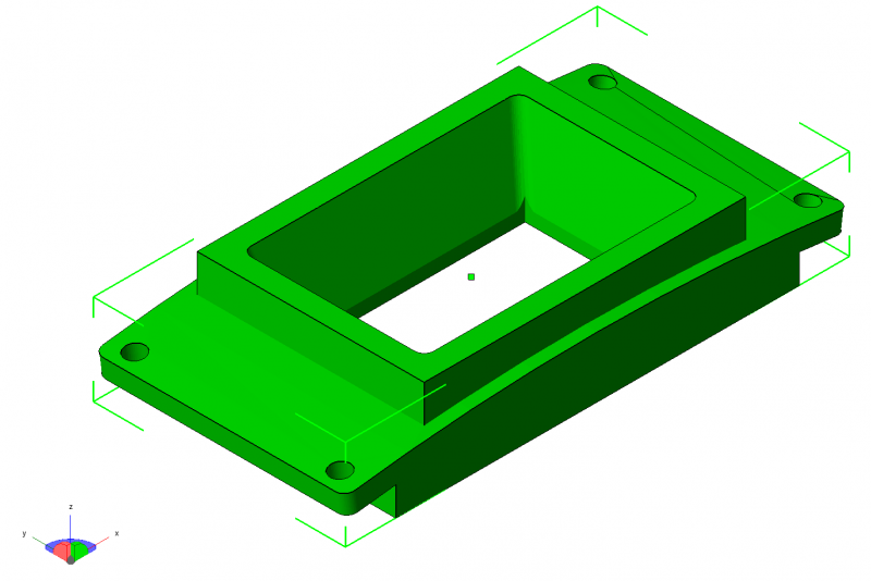
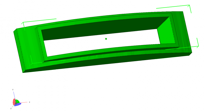
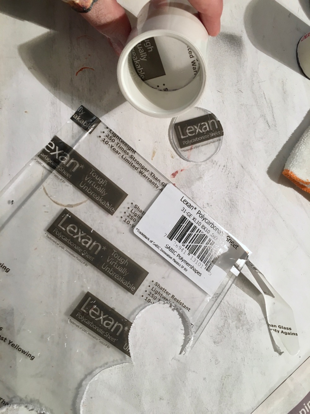
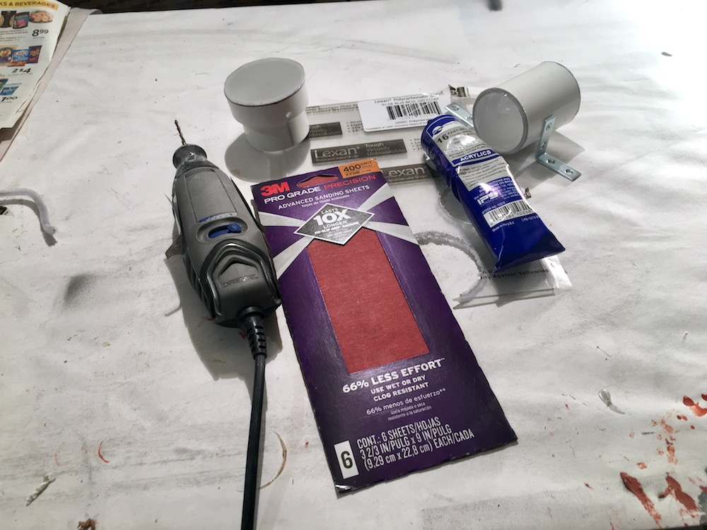
To mount R2’s PSIs (Process State Indicators), I purchased PVC couplings that the PSIs fit into. To create a lens for the PSIs, I purchased a small sheet of lexan, cut it out to fit the PVC coupling, and sanded one side of it with 400 grit sandpaper to rough it up. I also placed a cotton ball in there to really diffuse the light.
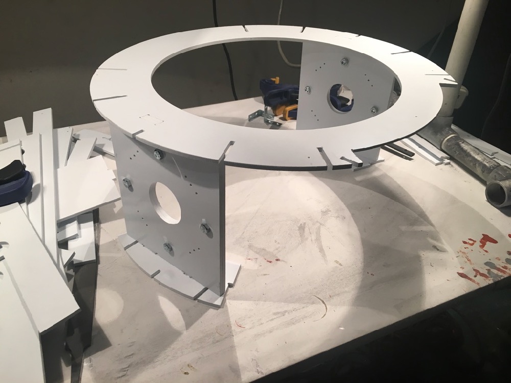
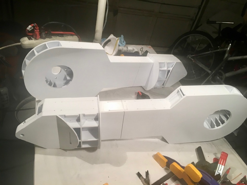
Body, Legs, & Feet Construction
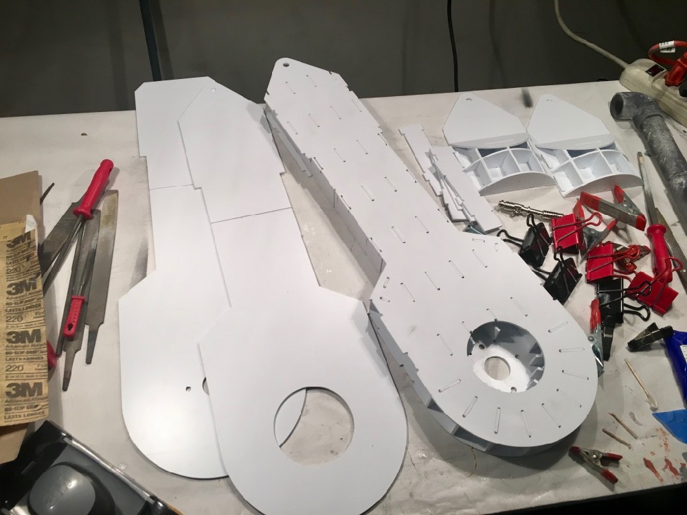
Fortunately, Frank at Media Conversions has some very detailed instructions on his website. I simply followed his recommendations and steps, and before long, I had an R2 body, legs, and feet.
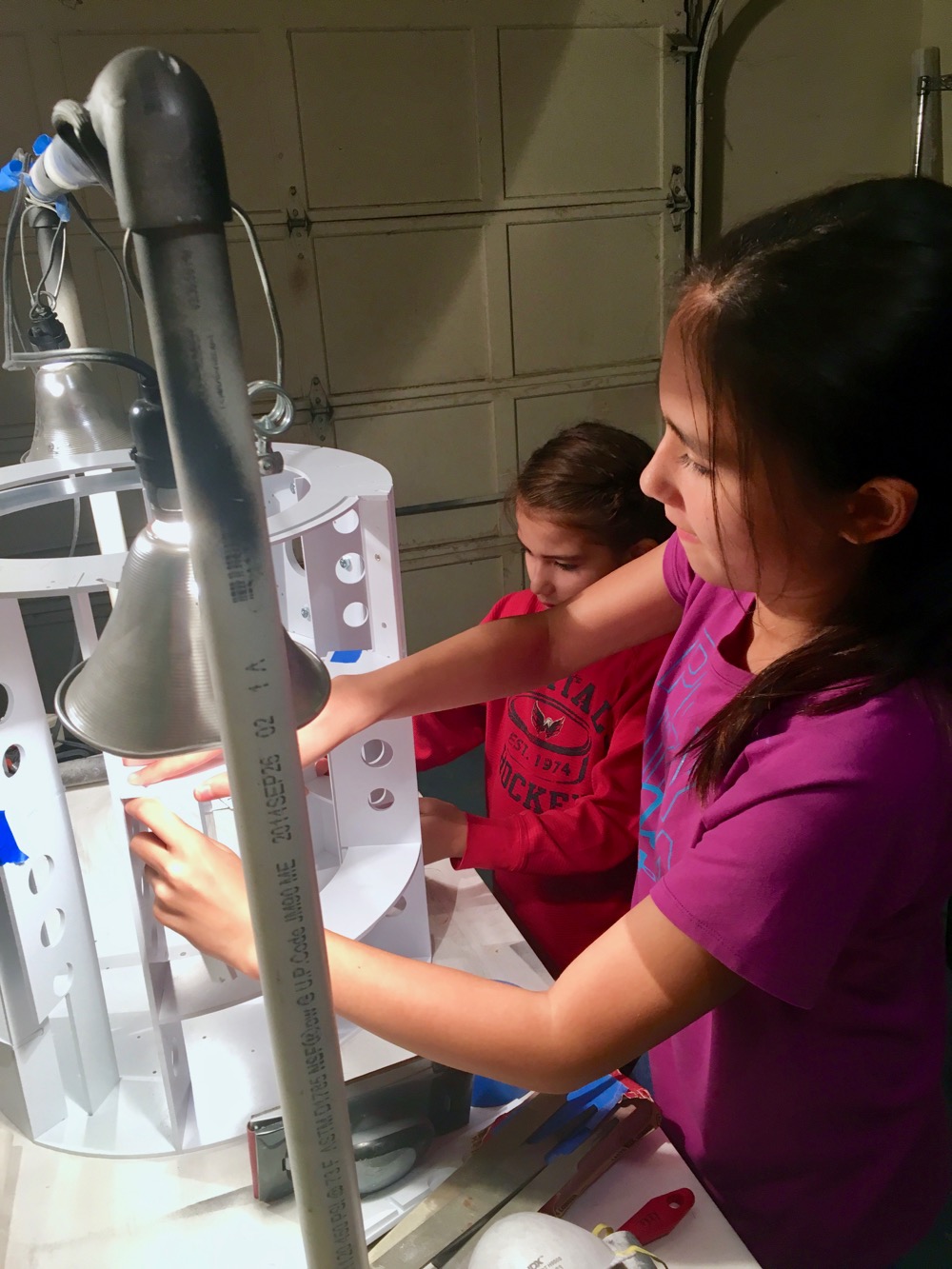
I chose to start the body first. Frank’s instructions were spot on. My 2 daughters were able to help build R2. Next, we built the legs, followed by the feet.
We had to continue printing out R2’s greeblies for his body…there are a lot of them! Arms, vents, ports, boosters, ankle cylinders…get lots of filament! They will need to be finished too.
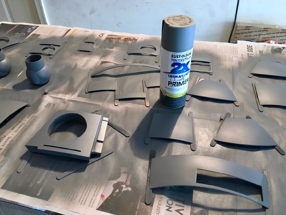
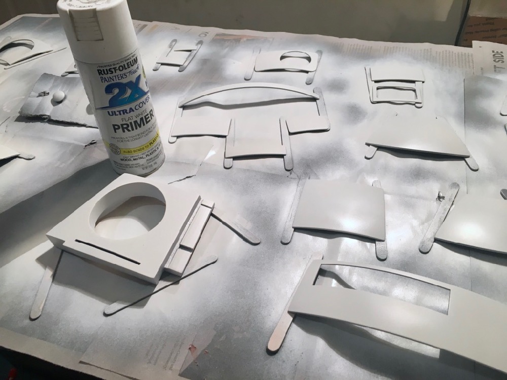
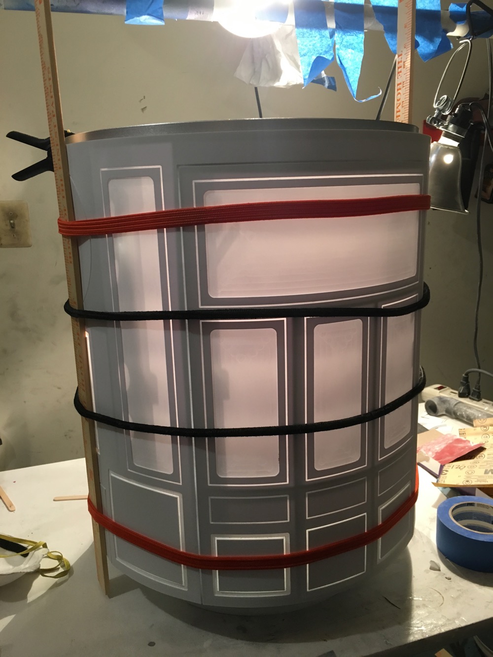
Because I had a few putty spots and repairs, R2 wasn’t completely white when he was built. I ended up priming EVERYTHING with gray primer, wet-sanded it with 800 grit, hit it with tack cloth, and then spraying it with Rustoleum Satin White.
Foot Drive Modification
I did have to deviate a bit from Frank’s plans when it came to the drive system. I followed his instructions for using a scooter motor and 2 inline Colson wheels in each foot. When doing this, R2 had tremendous difficulty turning. I checked on the Astromech forums and saw that other builders simply using a caster wheel behind the drive wheel.
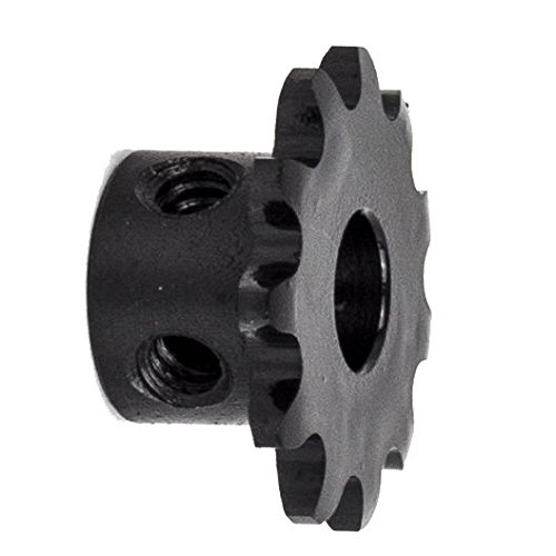
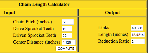
My goal was to get a caster wheel on each of the feet without having to modify R2’s feet too much. Getting rid of the back wheels meant, shortening the drive chain. I used a sprocket/chain calculator online and calculated the length of the chains that would be needed. I measured the distance from the center of the front wheel axel to the center of the “jackshaft”. One foot was 3-1/8″ (3.125″) and the other foot was 4-1/8″ (4.125″). I tried to get as close to an even number as I could to minimize the slack in the chain. What seemed to work best was using an 11 tooth sprocket with hub on the jackshaft (replaced the 9 tooth). I found some on Amazon with 2 set screws.
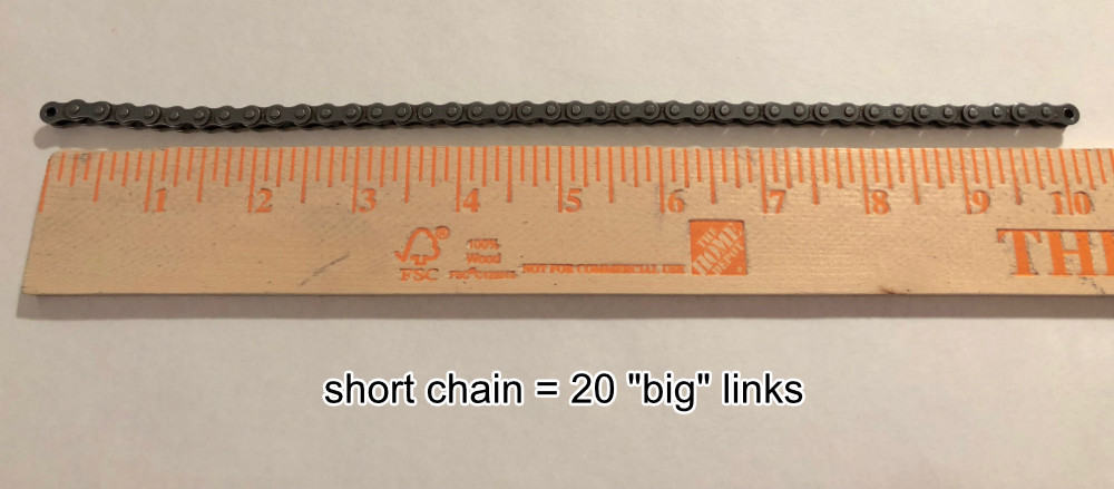
For the foot with the shorter distance from the center of the jackshaft to the center of the front axel, the calculator showed:
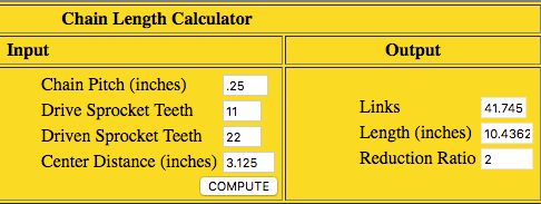
The calculator counts ALL links, the inside and larger outside links. As you can see from the image, it calls for just shy of 42 links. So, that is 21 “inside” links, and 20 regular outside links PLUS the chain link, bringing the total links to 42. I recut my chain to have 20 regular links.
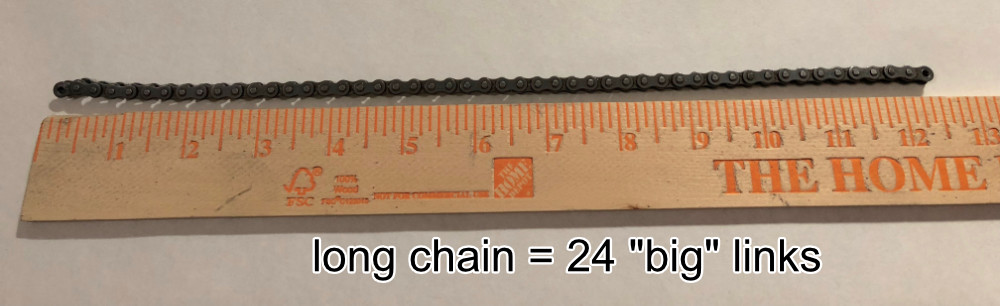
The other foot has a slightly longer distance between the center of the jackshaft axel and the center of the front wheel axel. It measures 4-1/8″ (4.125″). Plugging that into the calculator shows the following:
I cut the chain to have 24 “big” links, leaving 25 inside links, and room for the actual link, making the total 50 links:
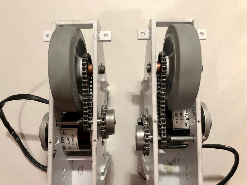
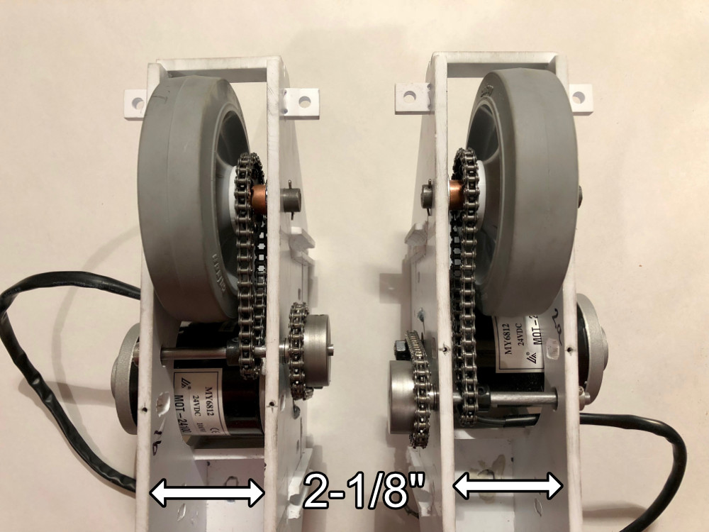
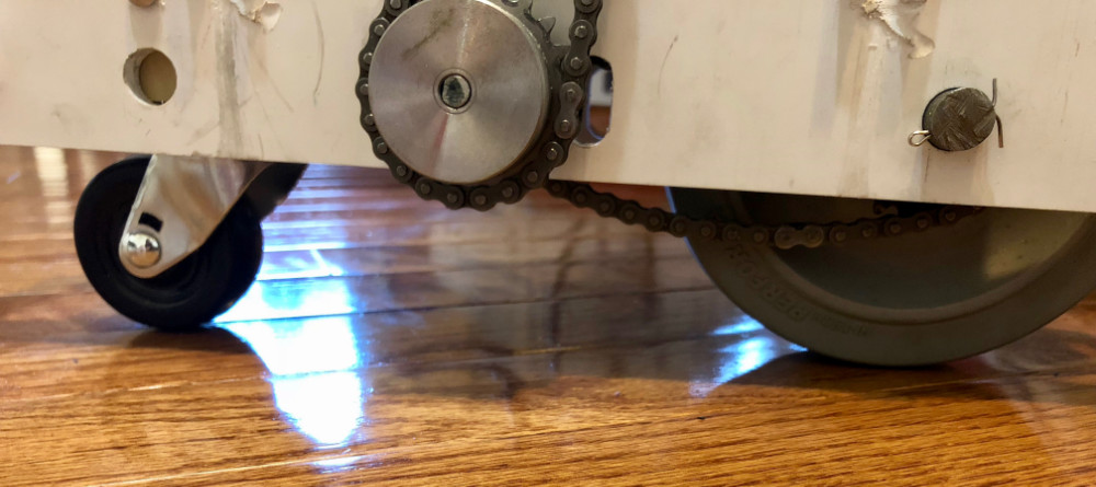
The chain tensioner was removed. There is a tiny bit of slack on the chains from the jackshaft to the front drive wheel, however, it is not enough for the links to jump/skip. Here is a photo of the newly cut chains in place:
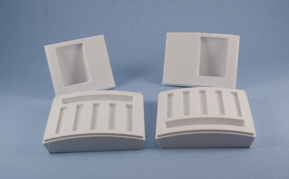
Now that the drive has been taken care of, its time to get that rear caster wheel attached. Measuring the distance between the 2 plastic plates on the foot shell yields 2-1/8″.
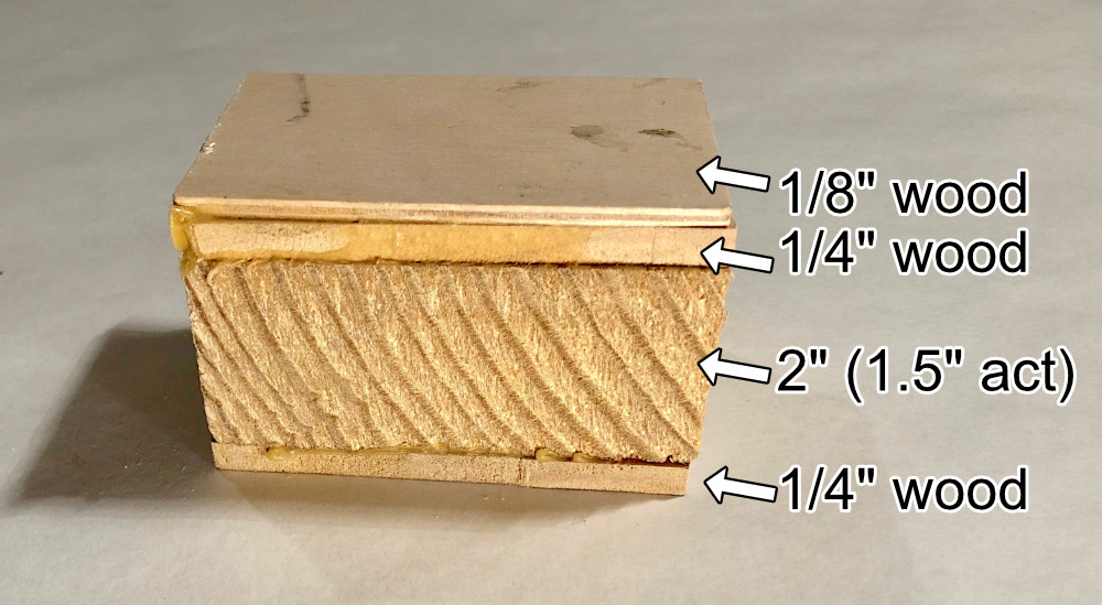
I used a few different types of wood to fill that space. For the main support piece, I had some extra 2 x 8″ board lying around. You probably know that 2 x 8″ wood isn’t really 2″, it is 1.5″ actual. So I had 1.5″ accounted for. I cut the 2×8″ wood to the length my caster wheel. Once it was cut, I slapped a 1/4″ piece of wood on each side, giving me 2″. I found some 1/8″ wood at Michael’s craft store, and it gave a nice snug fit inside the wheel shell.
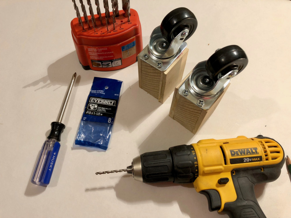
I mounted the casters to the newly created wood block by drilling a 9/64ths inch pilot hole for #10 x 1-1/2″ screws:
You want to be sure that the caster can swivel freely, and not hit the sides of the plastic casing.
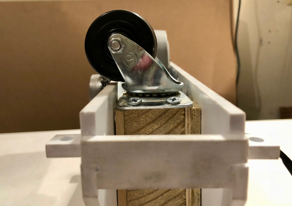
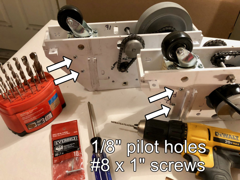
With the wood block and casters in place, I drilled 2 pilot holes on each side of the plastic/wood to secure it. I drilled a 1/8″ pilot hole to accommodate #8 x 1″ screws. NOTE: keep the #8 screws inline with the unused axel hole…that way, the outer foot shell will slip over the foot drive without having to shave any plastic off of the bottom of the outer foot shell. The bottom of the outer foot shell already has clearance for the rear axel. Now that clearance will be used for the #8 screws. I used sheet metal screws (which are OK for wood/plastic). If you wanted to, I suppose you could use wood screws and sink the head.
It is not perfectly parallel to the floor, but it is not noticeable when driving around.
Now R2 can turn with ease!
Electronics
Thank goodness for Astromech.net. Many R2 builders have shared their knowledge and experience, to help rookies, like myself, learn the basics. Frank’s plans did include some instructions for using a radio control system for R2, but I chose to implement a more stealthy system, so that I could “drive” R2 while in costume. The S.H.A.D.O.W. system, detailed on Astromech.net, allows R2’s driver to use a Playstation 3 Move controller to issue commands via bluetooth to an Arduino control board. My R2 unit is pretty vanilla when compared to other builders. He moves, he makes noise, his dome rotates, and he lights up. For the time being, that’s all I want. The S.H.A.D.O.W. system offers this, and room for upgrades later on. S.H.A.D.O.W. is detailed here on the Astromech forums. I used the following electronics for controlling R2:
Completion
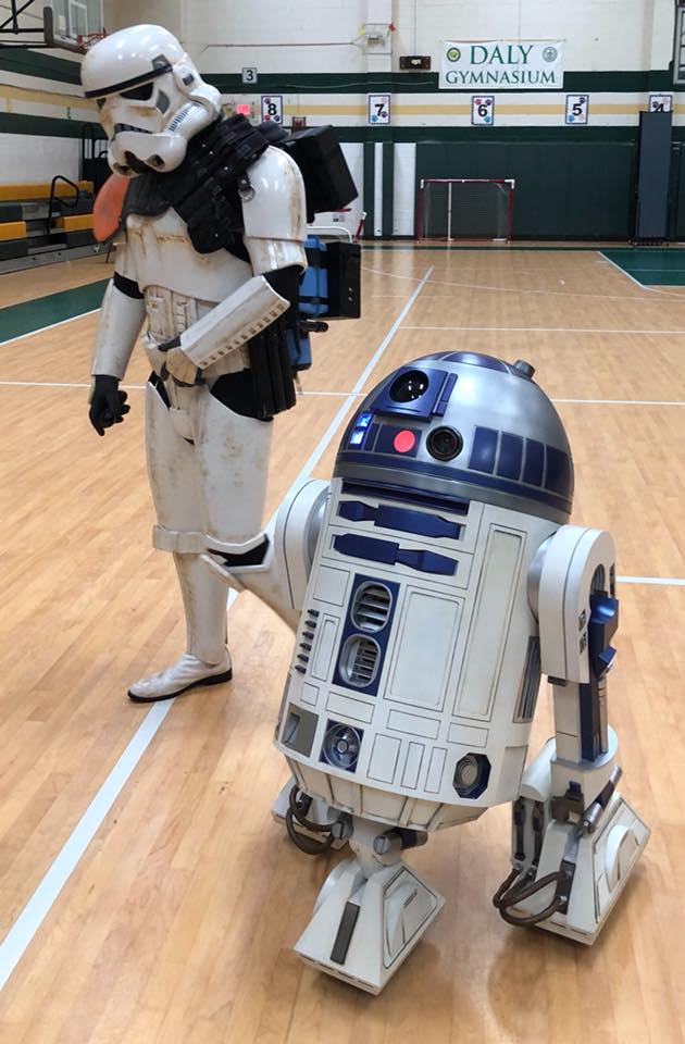
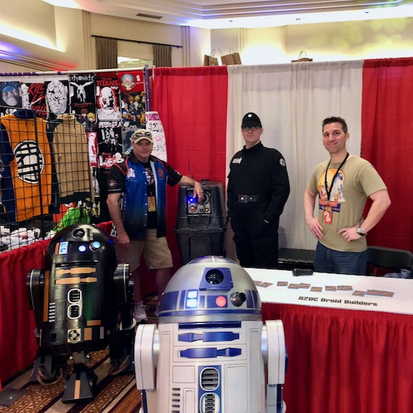
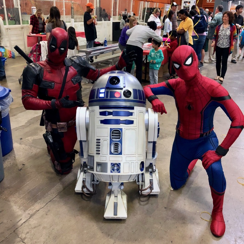
Building an R2 unit was a massive undertaking. It was not without its challenges. Mistakes were made. Things were put together improperly, re-painted…electronics were toasted. It was definitely a learning experience. Despite the mistakes that were made, I can honestly say that this is one of the most rewarding things that I’ve done in my life. I set a goal, learned stuff I never thought I’d learn, and achieved. Taking R2 out to meet other Star Wars & robotics fans is terrific fun. I am so happy to have taken this journey. R2 really pushed my limits, and I am grateful for that.
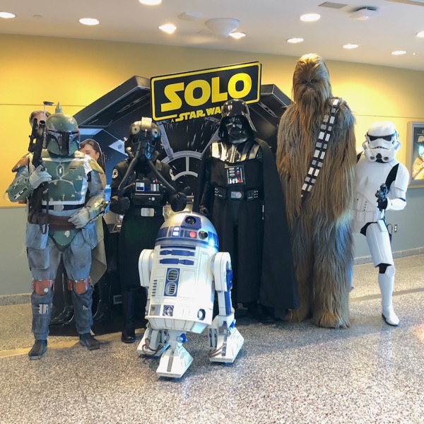

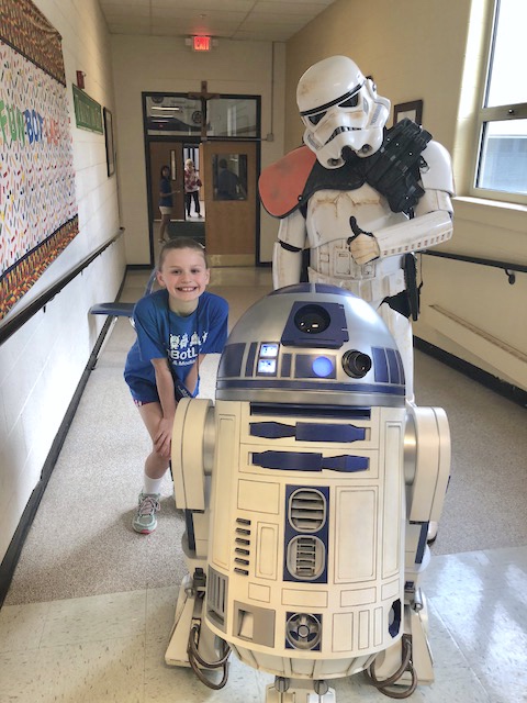
Awesome, A trooper finally got the droid he was looking for.